Measuring things are easy but keep track on them are hard. When we sick doctor ask us to measure the body temperature and record it but we are very reluctant do so. It is not just temperature but blood pressure, SPO2, heart beat, blood sugar level, LDL and HDL all of them are need to be recorded for future use.
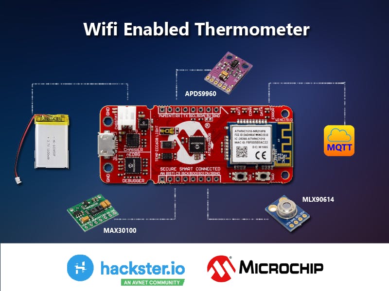
SolutionThe solution is pretty much easy thanks to Microchip AVR IoT GW board. The AVR IoT GW board is the heart and the brain of the solution. Here I hooked up 3 sensors to the system. MLX90614 IR contactless temperature sensors is to measure the patient's body temperature (specially when you are infected from some viruses such as Covid-19, measuring body temperature is very vital factor to diagnosis the disease) and MAX30100 pulse oximeter on the other hand is used measure the heart beat and blood oxygen saturation. As I mentioned previously measuring is not that hard but keep tracking those measurements are the difficult. Since AVR IoT GW is having a WIFI module, keep track of the measurements are not so difficult at all. The AVR IoT GW board collect all the sensor data and post those to Android mobile application via MQTT broker where we store all the data.
The AVR IoT GW board has many features, specially the li-po connector and the charging circuit makes my solution all portable so I thought to use this solution as a bed side emergency lamp so hooked up Neo LED ring (WS2412) and another sensor called APDS9960 gesture sensor. Using your hand gesture you can light on this device in any emergency situation. And also this device does not present any buttons, user can easily change the device operations using the hand gesture believe me this so convenient.
For example, if you move you hand top to bottom the device will lite up then move your hand bottom to up will turn off the light. To enter the temperature measurement mode what do you have to do just move your hand left to right on the sensor. By doing opposite the device will be put on heart beat capture mode.
Let's see how I built this....
My name is Chamal Ayesh Wickramanyaka, I am a software engineer who has passion in IoT ready to make changes. Before we begin I would like to mention some big names who are heavily investing on us to make these stuff. Hackster.io is the greatest platform we can show our true colors. Microchip the chip maker provides us this amazing dev boards. I will walk you through the steps by steps manner so you can follow me and recreate this.
Let's get to know AVR IoT WGIt is Microchip one of development board with ATMega4808 microcontroller. Apart from the microcontroller it has 2 built-in sensors (TEMT6000 light sensor and MCP9808 temperature sensor), crypto processor and WIFI module and out of box it supports Google IoT platform with authentication. You can find more information here.
This boards supports Atmel Studio and MPLAB X IDE. These are great tools to program AVR IoT WG. Here in this project I am showing you how to use Arduino IDE to program this board. This board is so versatile you can use any IDE to program it. Since the board is new we do not have much sensor drivers out there to use in MPLAB X IDE and the board is compatible with mikroBUS eco system, creating sensor drivers (libraries) outside the eco system is pointless.
Installing AVR IoT WG in Arduino IDEFirst thing you have to have Arduino IDE install in your computer then add the AVR IoT WG into the IDE.
Add board definition into the preference list
https://mcudude.github.io/MegaCoreX/package_MCUdude_MegaCoreX_index.jsonThe add the board by searching for "MegaCoreX"
For additional information here is the best place to start.
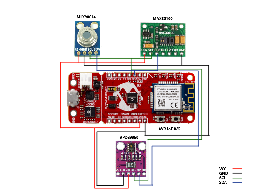
Connecting MLX90614 with the boardThe wire connection pretty much easy, you have to connect matching pairs such as sensor VCC to board 3.3v, sensor GND to board GND, sensor SCL to board SCL and sensor SDA to board SDA. This is the I2C (TWI) communication. Then upload the code into the board and observe the result.
Go to library manager and search for "MLX90614" and install it. You can find more information under this GitHub repository
#include <Wire.h>
#include <Adafruit_MLX90614.h>
Adafruit_MLX90614 mlx = Adafruit_MLX90614();
void setup() {
Serial2.begin(9600);
Serial2.println("Adafruit MLX90614 test");
mlx.begin();
}
void loop() {
Serial2.print("Ambient = "); Serial2.print(mlx.readAmbientTempC());
Serial2.print("*C\tObject = "); Serial2.print(mlx.readObjectTempC()); Serial2.println("*C");
Serial2.print("Ambient = "); Serial2.print(mlx.readAmbientTempF());
Serial2.print("*F\tObject = "); Serial2.print(mlx.readObjectTempF()); Serial2.println("*F");
Serial2.println();
delay(500);
}
Make sure to use "Serial2" instead of "Serial".
If you are happy with the outcome let's get going.
Connecting MAX30100 with the boardWhen you connecting the MAX30100 with the AVR IoT WG, first thing you have to do is to remove the pull-up resistors from the sensor breakout board.
Go to library manager and search for "MAX30100lib" and install it. Follow the link to find more information. The wire connections are straightforward as previous. The sensor is using the same I2C bus.
#include <Wire.h>
#include "MAX30100_PulseOximeter.h"
#define REPORTING_PERIOD_MS     1000
PulseOximeter pox;
uint32_t tsLastReport = 0;
void onBeatDetected()
{
Serial2.println("Beat!");
}
void setup()
{
Serial2.begin(115200);
Serial2.print("Initializing pulse oximeter..");
if (!pox.begin()) {
Serial2.println("FAILED");
for(;;);
} else {
Serial2.println("SUCCESS");
}
pox.setOnBeatDetectedCallback(onBeatDetected);
}
void loop()
{
pox.update();
if (millis() - tsLastReport > REPORTING_PERIOD_MS) {
Serial2.print("Heart rate:");
Serial2.print(pox.getHeartRate());
Serial2.print("bpm / SpO2:");
Serial2.print(pox.getSpO2());
Serial2.println("%");
tsLastReport = millis();
}
}This is the gesture sensor used to capture use hand movements and it executes different command according to the hand gesture. This is also used I2C communication therefore the wiring as the same as previous sensors.
VCC to board 3.3v, sensor GND to board GND, sensor SCL to board SCL and sensor SDA to board SDA.
Go to library manage and search for "Adafruit_APDS9960" and install it.
Upload below code in to the board and observe the result in the serial monitor.
#include "Adafruit_APDS9960.h"
Adafruit_APDS9960 apds;
// the setup function runs once when you press reset or power the board
void setup() {
Serial2.begin(115200);
if(!apds.begin()){
Serial2.println("failed to initialize device! Please check your wiring.");
}
else Serial2.println("Device initialized!");
//gesture mode will be entered once proximity mode senses something close
apds.enableProximity(true);
apds.enableGesture(true);
}
// the loop function runs over and over again forever
void loop() {
//read a gesture from the device
uint8_t gesture = apds.readGesture();
if(gesture == APDS9960_DOWN) Serial2.println("v");
if(gesture == APDS9960_UP) Serial2.println("^");
if(gesture == APDS9960_LEFT) Serial2.println("<");
if(gesture == APDS9960_RIGHT) Serial2.println(">");
}
Please give attention to the "Serial" keyword, it is "Serial2" not "Serial" as normal Arduino UNO board.
Onboard temperature and light sensorsThis is worth to mention the built-in sensors on the AVR IoT WG board.
- MCP9808 temperature sensor
- TEMT6000 light sensor
It is so simple to integrate the light sensor with analogRead() below is the code.
#define LIGHTSENSORPIN          (PIN_PD5)
int reading = analogRead(LIGHTSENSORPIN);
float light_value = reading / 1023.0 * 100;
Serial2.println("Light intensity: " + light_value);
For MCP9808 sensor you have to have installed "Adafruit_MCP9808" library using library manager. The code for the sensor as follows,
#include "Adafruit_MCP9808.h"
#define MCP9808_ADDR            (0x18)
Adafruit_MCP9808 tempsensor = Adafruit_MCP9808();
tempsensor.setResolution(0);
tempsensor.wake();
float c = tempsensor.readTempC();
float f = tempsensor.readTempF();
Serial2.print("Temp: ");
Serial2.print(c, 4); Serial2.print("*C\t and ");
Serial2.print(f, 4); Serial2.println("*F.");This module employs SPI bus for communication. You have to install the "WIFI101" and "PubSubClient" library. I used below code to establish connection with my router.
#include <SPI.h>
#include <WiFi101.h>
#include <PubSubClient.h>
char ssid[] = "YOUR_SSID";
char pass[] = "YOUR WIFI PASSWORD";
int status = WL_IDLE_STATUS;
WiFiClient wificlient;
PubSubClient mqttclient(wificlient);
void setup() {
//Wire.begin();
Serial2.begin(115200);
WiFi.setPins(PIN_PA7, PIN_PF2, PIN_PA1, PIN_PF3);
if (WiFi.status() == WL_NO_SHIELD) {
Serial2.println("WiFi shield not present");
// don't continue:
while (true);
}
while (status != WL_CONNECTED) {
Serial2.print("Attempting to connect to SSID: ");
Serial2.println(ssid);
status = WiFi.begin(ssid, pass);
}
Serial2.println("Connected to wifi");
printWiFiStatus();
mqttclient.setServer("MQTT SERVER", PORT); // Use to connect to MQTT
mqttclient.connect("MedicalDevice001"); // Use to connect to MQTT
}
void printWiFiStatus() {
// print the SSID of the network you're attached to:
Serial2.print("SSID: ");
Serial2.println(WiFi.SSID());
// print your WiFi shield's IP address:
IPAddress ip = WiFi.localIP();
Serial2.print("IP Address: ");
Serial2.println(ip);
// print the received signal strength:
long rssi = WiFi.RSSI();
Serial2.print("signal strength (RSSI):");
Serial2.print(rssi);
Serial2.println(" dBm");
}This project primary goal is to show sensors values (body vitals) in Android smart phone so we need a way to make this happen. I used MQTT broker for this. You have couple of ways to have a MQTT broker (server). One way is to purchase one from Google or AWS or you can have your own MQTT broker. Follow this link to get more information on MQTT
If you want to have your own MQTT server (like me) first thing is you should have a cloud server. I am using a Linode cloud server (it is very economical only $5 per month and you can terminate the service at any given time) with Ubuntu installed. Here you can find the steps to install EMQ X server in ubuntu.
Once your MQTT server is ready you can start publishing data to the server using below code.
// This is to publish light sensor data into the server
int reading = analogRead(LIGHTSENSORPIN);
float light_value = reading / 1023.0 * 100;
if (mqttclient.connect("MedicalDevice001")) {
String str_light = (String) light_value;
char char_light[5];
str_light.toCharArray(char_light, 5);
mqttclient.publish("light", char_light);
}My device does not have a display so I used RGB LED ring to indicate different modes (a.k.a Moods) in the device. Using library manager search and install "Adafruit_NeoPixel" then use below code snippet to manipulate LED according to your choice.
#include <Adafruit_NeoPixel.h>
#define NUMPIXELS               24
#define PIN                     (PIN_PD4)
Adafruit_NeoPixel pixels(NUMPIXELS, PIN, NEO_GRB + NEO_KHZ800);
void setup() {
pixels.begin();
pixels.show();
for(int i=0; i<NUMPIXELS; i++) {
pixels.setPixelColor(i, pixels.Color(150, 150, 150));
}
pixels.show();
}This is quit simple Android application developed using Kotlin. It's s pretty easy language to learn. I used Paho library to make the communication with the MQTT broker. You can find all the information here for paho. It is quit hard to explain how I developed the Android app in this project, if I do so this will be very lengthy and boring. I am planning do a another project to explain my Android project. But for your reference and completeness of this project I uploaded the entire Android project into the GitHub. Use Android Studio to view and modify the project. If you have any doubt please feel free share in comment section. I will try my best clear your doubts.
Conclusion
If you have came this far, I would love to give you my sincere thanks and I am very grateful. This is a quite lengthy project and I would be able to use all of my knowledge to this project. As you can see here I have almost all the embedded system communication buses such as I2C, SPI, UART, and analogRead. You can find the complete project *.ino (Arduino sketch) here.


_1x_bGT19vVAby.png?auto=compress%2Cformat&w=40&h=40&fit=fillmax&bg=fff&dpr=2)


_3u05Tpwasz.png?auto=compress%2Cformat&w=40&h=40&fit=fillmax&bg=fff&dpr=2)
Comments