


Hardware components | ||||||
| × | 1 | ||||
 |
| × | 1 | |||
 |
| × | 1 | |||
 |
| × | 5 | |||
| × | 4 | ||||
 |
| × | 4 | |||
 |
| × | 3 | |||
 |
| × | 4 | |||
Hand tools and fabrication machines | ||||||
 |
| |||||
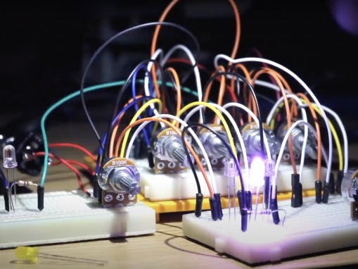
I started this project after spending a lot of time online staring at other peoples modular synthesisers. I ended up diving deep into electronics research, and decided that it would be fun (and cost-efficient) to try to build my own! This is the first module I have created, and it makes some gorgeous ambient sounds (which you can hear in my video).
The Auduino works by creating two triangle waves with pitch and decay knobs, which you turn and tune to form interesting harmonics. The singular knob to the left of my Auduino affects the frequency of the repetition of a grain of this noise – this means that you can tune it to a wide variety of pitches from deep bass growls to high pitched ambient squeals. The code which runs it is relatively simple, and very well noted, and therefore this makes a great project for someone perhaps looking into changing the code up too!
Parts ListPart#NotesStripboard1At least 17×20 dots, but more space means you could add more upgrades laterArduino Nano1WireI used recycled wire from inside an old cable100k Potentiometers5Can be anywhere between 10-100k, just make sure they’re the same6.35mm Audio Jacks4If you have a modular system that uses 3.5mm, those work fine too.LEDs4I used purple, use whatever you like!Light Dependent Resistors3560Ohm Resistors4(I replaced the one on my external LED with a 4.7k resistor to dim it, as I used ultrabright LEDs)Enclosure1I used a biscuit box, anything that fits the components in will work!Solder
Building the Auduino1. Breadboarding the Basic CircuitBefore I started trying to come up with a permanent version of the circuit, I made sure to test everything out on a breadboard. This allowed me to think about my CV controls, which first started as an experimental light theremin control.
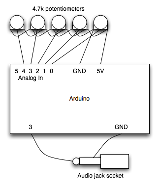
– All the potentiometers are connected to 5v on one side, and ground on the other side.
– The centre pin on each potentiometer is connected to (respectively) Arduinos analog inputs 0, 1, 2, 3, and 4.
– The audio out jack is connected to ground from its ground pin, and to the Arduinos digital out 3 from its signal pin(s).
– The LED is connected to ground from its ground pin, and to the Arduinos digital out 13 from it’s positive pin.
2. Creating the EnclosureTo create the enclosure for my Auduino, all I did was drill some appropriately sized holes into a wooden box. I also used sticky back velcro to stick the stripboard to the bottom of the box, to stop it from rolling around during use. I also painted the top of the wood using acrylic paint, and 3D printed some ‘Moog style potentiometer knobs’ from Thingiverse.
You could use anything as your enclosure! I would be interested in seeing any cool experimental enclosures people come up with for this thing!
3. Making a homemade CV VactrolIn my circuit, I have included some very basic DIY Vactrols to give this thing CV inputs. These isolate the circuit from the input, and stop any issues if you were to plug something into it with the wrong voltage somehow. They also add a bit of ‘ambient niceness’ to the CV control!
For this bit, you’ll need 3 of your LEDs, and your 3 Light Dependent Resistors (LDRs).
– If your LED has a curved top, you can file it flat using sandpaper or a nail file. This allows it to get more solid contact between it and the LDR when you stick them together.
– Place the two pieces facing each other, and wrap them up in electrical tape (or use heat shrink, if you’re more prepared). One tip is to cut the negative leg on the LED even shorter, so that you can tell which side of the vactrol is which.
– Try to make them as isolated as possible, so that no external light gets in.
The way which you add these to the circuit is to bridge them over the potentiometers.
– The positive leg of the LDR receives power from the Arduino.
– The negative leg of the LDR goes to the same signal pin as the potentiometer you want it to affect (I chose the main grain frequency (Analog pin 0), and the two individual wave pitches (Analog pins 3 and 1)).
– The positive leg of the LED is connected to the signal pin on the audio jack, and will be powered by the CV that you put into it.
– The ground led of the LED is connected to the ground on its corresponding audio jack. (not the ground for the rest of the circuit, this is providing the isolation)
4. Wiring and SolderingOnce you have mounted everything into your enclosure, made your vactrols, and wired everything together – it is time to solder. I did this in sections so that I could remember what I was doing.
5. Playing your Synth!Now, take some time to play with the awesome sounds that the Auduino can make!
—
Thanks so much for reading, there is further visual information in my youtube video – and also links to others work I found useful along this journey! If you need any further help, I am happy to answer any comments!
ReferencesThe Auduino Wiki (code here) code.google.com/archive/p/tinkerit/wikis/Auduino.wiki
Peter Knight first Demoing the Auduino vimeo.com/2944731
Notes and Volts notesandvolts.com/2014/07/build-auduino-granular-synth-part-1.html
Joshua AC Newman github.com/JoshuaACNewman/Auduino2
Joshua AC Newman glyphpress.com/talk/2018/build-a-scion
Potentiometer Knobs www.thingiverse.com/thing:2563351


Comments
Please log in or sign up to comment.