


Hardware components | ||||||
| × | 1 | ||||
| × | 1 | ||||
| × | 1 | ||||
| × | 1 | ||||
| × | 1 | ||||
| × | 1 | ||||
| × | 2 | ||||
| × | 1 | ||||
| × | 1 | ||||
| × | 1 | ||||
| × | 1 | ||||
| × | 1 | ||||
Software apps and online services | ||||||
 |
| |||||
Put'n'Play CubeDescription
Have you ever seen a child crying and asking you why their favourite CDs don’t play anymore? CDs are a vulnerable medium suffering from scratches when children are handling them. We run crazy sorting CDs into their cases and replacing non-working ones. By the way, don’t expect a toddler to successfully use a CD player from the very beginning.
The idea of the Put’n’Play Cube was born… by ripping the children songs or radio plays and storing them on a MP3 player. The goal was to make the use of the toy as intuitive as possible, with a minimum number of buttons, portable and cheap, as small as possible and with an innovative interaction to trigger the songs they want to play. Further, we insisted from the very beginning to allow a personalised design of the player and the freedom to use any beloved characters or items of the kids in order to trigger the right song.
DetailsThis project is gradually improving. It is fully functional at this point, our kids use it already every day. Nevertheless, we have planned several improvement for the second release, such as a night light mode.
Features- 3D-printed case covered with felt with a personalised embroidery
- SD card for storing MP3 files
- Charging and uploading files via micro USB
- Visual feedback using 24x LED ring with configurable RGB pattern
- Triggering songs/folders using RFID module
- Creating your own characters and link them to a MP3 folder
- Pre-configuring maximum volume level
- Sleep mode for battery saving
- Customisable startup jingle
- Portable with a more than 20 hours of play time
- Cheap and easy to build hardware
Hardware
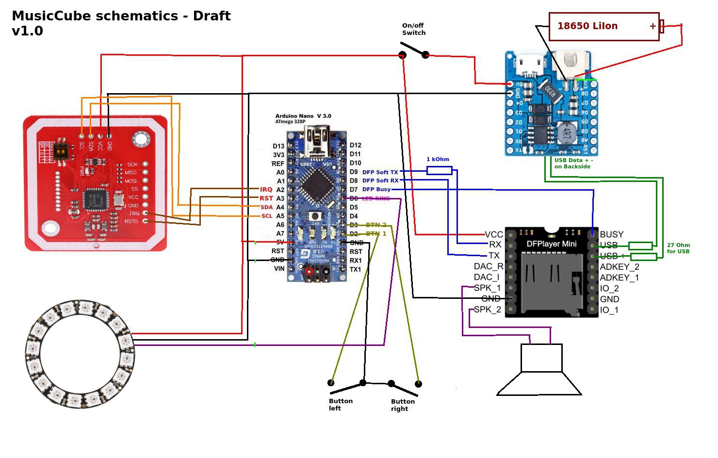
The Put'n'Play Cube hardware is based on the cheap DFPlayer module which contains an SD-Card reader, an MP3 decoder and an audio amplifier, controlable via a serial interface.
A Mifare compatible RFID reader is used to program and read the objects/characters that are placed on the cube. These objects are linked to the folders on the SD-Card containing the related mp3 files. Visual feedback such as state, played track etc. is done using a ring with 24 WS2812 RGB LEDs. An Arduino nano is used to control the mp3 player, handle the tags on the RFID reader, read the buttons and control the LEDs. We use a standard 18650 LiIon cell for many hours of autonomous music. There is even room for a second cell to double the runtime. The WEMOS Battery Shield provides us with stable 5V from the battery as well as doing all the charging and battery protection logic. The onboard Micro USB port allows us to charge the cube with any mobile phone charger. When connected to the USB port of a computer, the cube will register its self as a mass storage device to fill the SD Card with fresh music.
The mechanical and electronical assembly is done by soldering all components to a simple prototyping PCB. No custom PCB is needed. If you place everything correctly, it will perfectly fit the 3D-printed case. Simply follow the build instructions below.
All components can be bought from your/our favourite china shop or ebay at a low price.
Firmware
The firmware that is managing all functionalities of the cube is written in Arduino using several external libraries for the MP3 player, RFID reader and LED effects.
When the Cube is switched on, it checks for the SDCard, initializes the hardware while playing the configured startup jingle and startup led effects. Once that is done, the cube will wait for an RFID tag being placed on the reader.
If an already known tag is detected on the reader, the cube will speak the number on the tag and start playing the sd card folder named with the same number as programmed on the detected tag. The album will be resumed at the same track it was stoped last time. The LED ring will display the current track as well as a "play" effect.
If a new tag is detected, the cube will program this tag to the next available folder number. After programming it will tell the programmed number by saying the number twice. After that you will need to create the matching folder on the SD card and place the mp3 files in there. The next time when this tag is put on the cube, the corresponding folder will be played.
Short clicks on the left and right buttons will play the previous and next song in the current folder/album. Long presses of the buttons will decrease/increase the volume.
Build Instructions
Step 1
The case is composed of two halves. Depending on your printer settings it will take you about 6-7 hours to print all three parts. The case has been designed in a way that almost no support structures are required. We recommend to print only support for the three holes for the buttons and for the LED ring holder.
We have printed the case using PLA with the following printing parameters:
Infill: 15%Outside shellLayer height: 0,2mmNozzel: 0,4mm
Typically there is no need to glue the LED ring, it is designed so that you have to push is firmly on the case. Keep in mind that a small gap remains between the LED ring and the case. This is normal to make sure that the felt and volume fleece fits underneath.
You can find the STL files at thingiverse.
Step 2
The position where you put the breakout modules onto to prototyping board is important.
Solder the pin headers to the modules and place them in the correct position onto the prototyping board. Solder only one pin of each module and check if the USB ports and the SD card slot are accessible when the board is installed into the 3D-printed case. If everything is fine solder the remaining pins and do the connections according to the image below.
Step 3
Extract the content of the firmware zip file to your Arduino sketch folder. In the user settings section of the MusicCube.ino you can change some values to adapt the behaviors of the Put'n'Play Cube.
// -- user settings -------------
#define INIT_VOL      3
#define MIN_VOL       2
#define MAX_VOL       20 // max=30
#define STORE_TRACK   true
#define SAY_FOLDER    true
#define REPEAT_FOLDER false
#define STARTUP_SOUND 200
#define CYCLE_DELAY   20
#define SECS_UNTIL_SLEEP 1200L // sleep after 20min
#define LONG_PRESS_CYCLES 5
#define EFFECT_BOOT   FX_MODE_RAINBOW_CYCLE
#define EFFECT_PLAY   FX_MODE_COMET
#define EFFECT_IDLE   FX_MODE_BREATH
#define COLOR_MAIN    0,0,255
#define COLOR_TRACK   255,0,255
#define BRIGHTNESS    100
Line 1 - 3 is to set the speaker volume.STORE_TRACK can be set to true to resume from the last played track of a folder.If SAY_FOLDER is enabled the folder number will be said by the cube when a socket is placed on the cube.REPEAT_FOLDER is to enable loop playback.STARTUP_SOUND is the number of the mp3 file that is played when powering the cube.CYCLE_DELAY is used to control the speed of the LED ring effects.SECS_UNTIL_SLEEP is used when to put the cube into sleep mode after the last track of a folder is played. Only works if REPEAT_FOLDER is false.LONG_PRESS_CYCLES influences the duration necessary to use the next/previous track buttons for volume control.EFFECT_* to show in different states of the cube. See the WS2812FX library for more info on the available effects.COLOR_MAIN color used for common LED ring feedbacks e.g. the color for the idle or playback effect.COLOR_TRACK RGB values to define the color that is used to show the track number of the current playback.BRIGHTNESS a value from 0-255 to control the LED ring brightness.
After uploading the firmware to the Arduino Nano you have to prepare the SD card for the first use. You can find a zip file for the folder structure of the SD card. It also includes mp3 files for the numbers from 0-100, that are used by the firmware to give spoken feedback about folder numbers. See the readme.txt in the SDCard.zip for details about the folder and track naming.
Step 4
For each character or object you print a socket. Each socket is composed of two parts, there is no need to glue them together. You can simply open them using two screw drivers. Stick a RFID tag to the bottom part. We experienced that it is best to use screws to tighten the character to the socket. If possible place the screws so that you can glue the magnet to the centre of the socket. For heavy characters use two magnets.<>
It might be necessary to fill the character with material. We used hot glue.
Step 5
Print the template and use it to cut the fabrics used to cover the case. The cover of the case is composed of 1mm felt and 2mm volume fleece to ensure a soft haptic of the cube. If you have the possibility to use a embroidery machine you an stitch the circles of the speaker and the icons/smiley for the buttons. Feel free to personalize the cube with additional embroideries but keep in mind not to stitch the area where the micro USB connector is located.
Before sewing the corners, you should use spray adhesive to keep both materials together. Sew the corners and use some velcro to close the button flap.
Now, put the cube into the cover and mark the locations of the LED ring and the micro USB connector. Remove the cube and use scissors to make the two wholes.
You are done! Enjoy the put´n´play cube! Your kids will love it.
FilesEmbroidery.zip: Cut templates for felt and embroidery files for different stitching machines.
Musiccube_Arduino_v0.3.zip: Arduino Code for the Put'n'Play Music Cube.Zip contains the whole Arduino Playground including the needed libraries.
CuttingPattern.svg: Cutting pattern for the felt cover of the cube. File includes proposition of stitched decoration.
SDCard.zip: SD Card content and readme for the Put'n'Play Music Cube.


Comments
Please log in or sign up to comment.