


Hardware components | ||||||
_ztBMuBhMHo.jpg?auto=compress%2Cformat&w=48&h=48&fit=fill&bg=ffffff) |
| × | 1 | |||
 |
| × | 1 | |||
 |
| × | 1 | |||
 |
| × | 1 | |||
Software apps and online services | ||||||
 |
| |||||
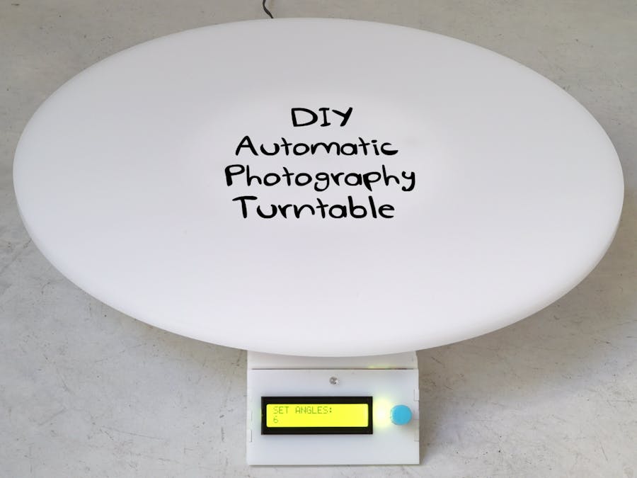
Photography turntables are round docks used by photographers to take images or videos of objects or people in 360°. The idea is that the object itself sits in the exact middle of the plate, while it spins, either manually or automatically, so you can get a good shot of the product from every angle.
What’s special about this photography turntable?
It’s automatic – the photography turntable is fully automatic, meaning that you don’t have to spin the table or click your camera
Camera-table sync – programmed to trigger both table and turntable (only for Cannon at the moment, sorry Nikon). Once you push the button, it both turns and triggers the camera, so you can sit and relax
Accurate and easy to setup – we used a stepper motor which gives you much higher accuracy and control over the angle you want to shoot
To start building the circuit, click here.
MechanicsLaser cut partsThe photography turntable has 4 Laser cut parts. We used white Plexiglass in 3 different thicknesses, depending on the part. Pololu offer an affordable laser-cutting service.
The parts are:
- Round plate – 10mm Plexiglass
- 2 Gears – 8 mm plexiglass
- Base casing – 3 mm plexiglass
You can find the .ai files on Thingiverse.
We designed the gears using geargenerator.com, then exported them to Illustrator and added drilling holes for screwing the pieces together.
In the small gear, we made the drill holes slightly smaller so it sits tightly on the stepper motor.
We used makercase to design the case and chose t-slots which we glued together. After designing the case, we exported the file to Illustrator, and made room for the LCD display.
Materials and toolsTo connect the plate, gears, and casing to one another you’ll need:
- Lazy Susan bearing
- 4 X M3 12mm screws
- 4 X M3 16mm screws
- 8 X M4 12mm screws
- 8 X M4 nuts
- 4 x M3 Brass threaded inserts
- 8 x M3 5mm Female Threaded Brass Hex Spacer OR 8 x M3 5mm Brass threaded inserts
Materials:
- Acrylic glue
- Super Glue
Tools:
- Electric drill
- Soldering iron
- Caliper
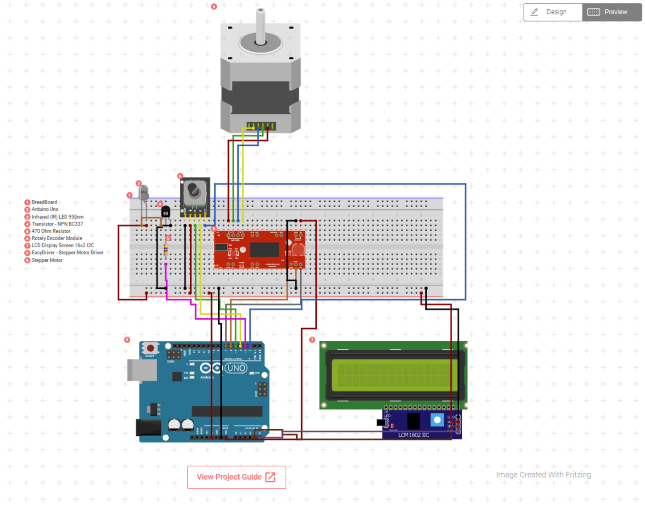
- Arduino Uno
- Stepper motor
- Rotary encoder
- LCD 16*2 I2C
- IR led
- easy driver
- Transistor + Resistor
- Female Barrel jack
Click here for the detailed wiring diagram.
For a step by step guide and for the code, go to Bill of Materials tab > click on "project guide”.
Once you verify everything is connected properly and working, you can make a small shield. Shields are better for permanent circuits and they are more compact. Breadboards, on the other hand, are good for testing and planning because you can connect and disconnect components easily.
Why we chose these components- Stepper motor – accurate and easy to use. Programming the stepper motor is much more simple because you can set it to count the number of steps between the angles.
- Infrared LED for camera trigger- we wanted a wireless connection with minimum setup. We found the IR code for a Canon camera and set it up accordingly. You can do the same for Nikon.
- Rotary encoder – we decided to go with a local option for the menu and add an LCD screen with a rotary encoder. You can also hookup a Wifi module and create an IoT dashboard to control the photography turntable wirelessly.
- Upload test code from circuito.io to check the circuit
- Visit Github repository
- Download photo-turntable.ino
- Copy code from line 16 (leaving “include libraries” and “pin definitions” from the original code)
- Make sure that the pins are set correctly
- Upload new code
The code implements a basic menu using a 16×2 LCD and a rotary encoder which also has a pushbutton.
Throughout the Firmware.ino you can see:
- pin declarations
- components settings
- constructors
- setup() function provided by circuito.io.
The loop function starts with reading the rotary encoders state, Left or Right, and its button as well.
The menu is implemented using a switch-case finite state machine – navigating through the different states:
VIDEO – enter video modeCHANGESPEED – set speed of the turntable 0-100%
- SPEED
- VIDSTART – start turntable in video mode
- VIDBACK – go back to HOME
STILLS – enter stills modeCHANGEANGLES – set number of angles
- ANGLES
- STILSTART – start turntable in stills mode
- STILBACK – go back to HOME
- HOME – idle
Toggle between states using the rotation of the encoder.
Select by clicking the button.
The two states: SPEED and ANGLES allow you to modify the variables responsible for the number of stop points in stills mode and the speed of rotation in video mode.
VIDSTART – calls the video() function:
- Sends the start recording IR code to the camera using the IR LED.
- Starts the table rotation at the chosen speed for a whole rotation.
- Sends stop recording IR code to camera using IR LED
Note:
For a smooth start and stop of the table, we implemented cubic acceleration and deceleration on the first and last 600 steps.
STILSTART – calls the stills() function.
- divides one full rotation by the number of set angles
- For each angle it sends the single stills shot IR code to the camera using the IR LED
- Starts the table rotation until reaching the next angle
Note – For a smooth start and stop of the table, we have implemented cubic acceleration and deceleration on the first and last 600 steps.
Putting it together- For quick and easy assembly, we used a Prototype Shield. This allows connecting the components and Arduino comfortably with jumper wires and male headers.
- Jumper Wire 2-pin – for the IR Led
- Jumper Wire 4-pin – for the LCD
- Jumper Wire 5-pin – for the Rotary Encoder
- To connect the power supply and Arduino we made an extension cord using a DC Barrel Jack Plug – Male and DC Barrel Jack – Panel Mount, soldering wires to ground and VCC between them. We connected the Panel Mount Barrel Jack to the back panel and the male to the Arduino. This way we can connect the power supply to the back wall.
Follow the instructions together with the images below:


_3u05Tpwasz.png?auto=compress%2Cformat&w=40&h=40&fit=fillmax&bg=fff&dpr=2)
Comments
Please log in or sign up to comment.