


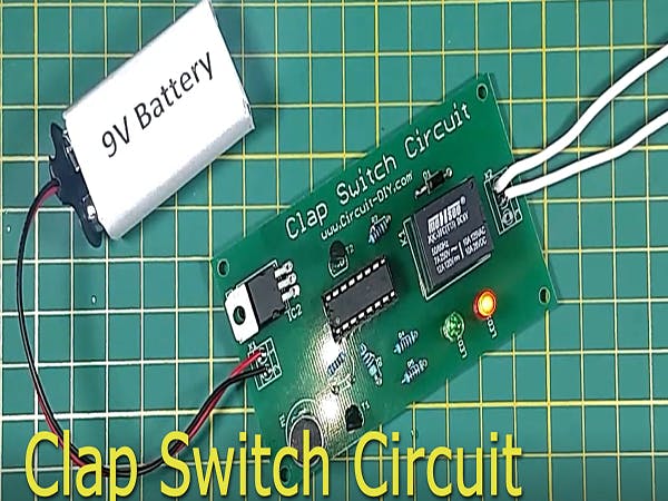
Clap switch circuits are simple circuits mostly used to fashion sound signals as electrical control signals. Electronics clap switches are used in places where dynamic control of machines/devices is preferred such as a sound-activated light responding to a knock on the door. So, in this project, we are going to design a simple DIY Clap Switch Circuit Using a CD4017 Counter IC.
Hardware RequiredTo Buy cheap Electronic Components please visit: UTSource
You will need the following parts to build this project
- Decade Counter IC CD4017
- Voltage Regulator IC LM7805
- SPDT Relay 5V/9V
- Condenser Mic
- IC Jacket
- NPN Transistor BC547
- AC Bulb/Lamp
- Resistors 22K, 1K, 470 Ohm
- Soldering Iron
- Soldering Flux
- DC Battery 9V
- Battery Clip
1) Solder 5V SPDT Relay onto the PCB Board
2) Solder the IC Jacket for CD4017 on the PCB Board
3) Solder the LM7805 Regulator IC on the PCB Board
4) Solder the LEDs and the 1N4007 diode on the PCB Board
5) Solder BC547 Transistors onto the PCB Board
6) Solder Resistors (R1, R2, R3, R4, R5)
7) Solder the condenser mic on the PCB Board
8) Solder Input (Battery Clips) & Output Connectors to the PCB Board
9) Trim any extra wiring
10) Connect the CD4107 IC & 9V battery, then power up the circuit
11) Test the circuit


Comments
Please log in or sign up to comment.