In a previous project we showed we showed how to use the Pulse Train Hat and wireless Xbox controller to control our Mecanum Bot.
Information and the project overview can be found on the following link:
https://www.hackster.io/cnc-design/pulse-train-hat-for-raspberry-pi-mecanum-bot-example-75fcd6
We now have created a platform on Hackster.IO for the Pulse Train Hat, if you could help us by becoming a member, then it would help us a lot as we need 25 members to get it featured.
https://www.hackster.io/pulse-train-hat
For this project, we want to add a few parts to the Mecanum Bot and also expand a little more on the design and the workings of it.
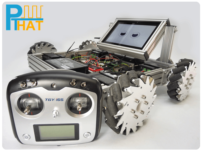
Here is a picture of the Mecanum Bot with extras added.
The Mecanum wheel is one design for a wheel which can move in any direction. It is sometimes called the Ilon wheel after its Swedish inventor, Bengt Ilon, who came up with the idea in 1973 when he was an engineer with the Swedish company Mecanum AB.
The angle between rollers axis and central wheel could have any value but in the case of conventional Swedish wheel it is 45”.The angled peripheral rollers translate a portion of the force in the rotational direction of ht wheel to a force normal to the wheel direction .Depending on each individual wheel direction and speed,the resulting combination of all these forces produce a total force vector in any desired direction thus allowing the platform to move freely in the direction of the resulting force vector,without changing of the wheels themselves.
After playing around for a few days with our Mecanum Bot, we decided that control over Wifi was a little restricted if we wanted our Bot to roam further a field and also reduce the amount of signal drop outs we were seeing.
So we started to look into RC transmitter and receivers and chose the Turnigy TGY-i6S Transmitter than came with a TGY-iA6B 6 channel receiver that gave PWM out on 6 individual channels.
The thing with RC receivers is that they do not simply give you a On or Off signal for each channel. They give out a PWM signal for each channel. This allows small servos usually found in RC airplanes, boats, cars etc to be easily controlled with minimum wiring as the standards are all in place.
There is also PPM receivers that put all six pulses on one channel, but we will focus on the dedicated six channel receiver that has one PWM for each channel at the moment.
The PWM signal is typically a pulse train running at a frequency of 50hz (50 pulses a second) and a pulse width of between 1-2 ms.
So for example a joystick would have a channel for each direction. When the joystick is in the center position it will give out a pulse width of 1.5ms, when it is fully pushed up it would give a pulse width of 2ms and fully down, a pulse width of 1ms. Between these points it will give linear range.
Now we probably could of got the Raspberry Pi to monitor these pulses and do the pulse width calculations of each channel, but we were not confident in the accuracy due to it already doing a lot of other things and also the GPIO pins on the Raspberry Pi are not 5 volt tolerant. So with this in mind we opted to get a cheap ARM module that could easily calculate the pulse width on each channel and also that had 5 volt tolerant pins.
We went for the STM32F103 minimum development board, that can be picked up on ebay and other places.
We can also supply one of these development boards already programmed with the RC Receiver code if needed.
As with all of the ARM STM32 family, the STM32F103 has loads of features, many of which we will not use. But hey it is low cost and does the job.
We have supplied the code compiled for this board and it can easily be programmed with a JTAG programmer or via a USB> Serial port adapter.
We tend to use the ST-Link V2 JTAG programmer, but that is because we are used to it and have it lying around.
Doing a quick google for Serial Programming STM32F103 minimum development board brings up a few links that show how it can be down other ways.
Once programmed, the code simply monitors each port and measures the pulse width of each channel from the receiver. It then sends the pulse width for all 6 channels in one packet via the USB port.
The USB port is configured as a HID device and is plug and play as far as Windows 10 IOT is concerned and no additional drivers are needed.
We thought it would be nice to get the exact reading of each channel, rather than just deciding if it was going to be a On or Off movement as we could then use the output for also varying the speed of the motors.
We opted to use the PA1-PA6 ports on the STM32F103 board as they are laid out next to each other and it means we can use a simple six wire connection loom straight over to the receiver for the Pulse Width readings.
Also we have 6 other pins that act as simple on/off switches, we can use of these for a keep alive that is connected to the PTHAT Emergency Stop input. These pin mappings are:
Channel1-PB14, Channel2-PB15 Channel3-PB5 Channel4-PB6 Channel5-PB7 Channel6-PB8
If any of these channels go over 155 reading then they take the Pin high.
For our keep alive signal, we are going to use Channel 6 which is controlled by a switch on the transmitter. When switched on it reads 200 and when off it reads 100. This means we can trigger the Emergency Stop using this switch, or if it looses signal.
We pull 5 volts and 0 volts from a 24V-5V regulator for the receiver and connect the Raspberry Pi via the USB port to the STM32F103 board.
Here is a picture of the wiring:We use Pulse Train Hat (PTHAT) for the Raspberry Pi for motor control.
Full details can found on the dedicated support site http://www.pthat.com
The PTHAT allows us to connect and control all four motors together or separately, supplying a nice clean pulse train and takes care of the ramping up and down routines automatically.
We use closed loop stepper motors that have great torque and also stay perfectly in sync.
At the moment they are connected directly to the Mecanum wheels via 8mm hubs. No suspension at the moment, but something we are looking at changing in the future.
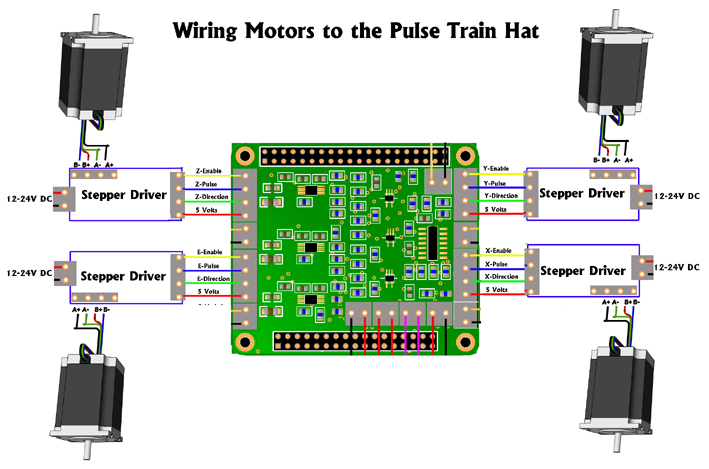
You can see below the wiring diagram.
We supply 24 volts to each motor driver and connect the Step, Direction and Enable lines back to the PTHAT, along with 5 volts.
We have used two 12V batteries wired in series to give us 24 volts to supply the motors.
Also there are two regulators for taking the 24 volts down to 5 volts. One supplies the Raspberry Pi and the other for the 10" Touch Screen and RC receiver.
We also have a voltage digital display, so we know when the batteries are getting low on charge.
The example application was developed in Visual Studio 2015 that can be used with Windows 10 IOT on the Raspberry Pi or compiled to x86/x64 for use on a PC.
It has been written in C# as a Universal Windows Platform (UWP).
I ran it up on the desktop to get a screen shot for now, and hence why it does not show the Raspberrry Pi serial port or the USB STM32F103 board.
We had a choice of running the software on the Raspberry Pi and then using the remote client to access it over WiFi and set certain parameters. But we decided to add a 10" universal LCD with HDMI interface and capacitive multi-touch input so we could do everything next to the machine. It also allowed up to have a bit of fun displaying animations that synced with the controller.
The application connects to the PTHAT via a serial connection and connects to the USB port for data coming in from the RC receiver channels, via the STM32F103 ARM board.
It reads each channels data that is coming in from the USB port and translates that into movements for each motor, depending on the direction and speed that the user of the RC transmitter chooses via the joysticks.
The movements are converted to PTHAT Instant Commands and sent out via the Raspberry Pi's USART. The PTHAT receives the commands and then controls the motors.
TestingNow some testing !
Gallery


Comments