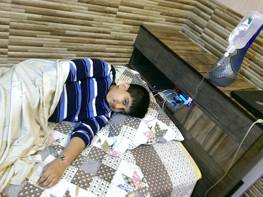
Every year many peoples die because of heart attack. only in United State 375,000 person die every year! there are many drug that calm down heart and prevent heart attack like nitroglycerin, ACE inhibitors, Beta blockers and ...! but they have to be injected to the body immediately. when an old lady sleeps at home and suddenly heart attack happens, she is really in a bad situation, because there is no doctor at home to help her and give her drug. and if she is hospitalized, it takes time for nurses to hear the alarm and go to patient's room, take her drug and inject that to the her body!
the first stage of heart attack is sudden change in heart beat rate. suddenly it goes too high or too low. at this stage we detect it and predict heart attack by help of a microcontroller and a heart rate sensor, then microcontroller will inject drug to body, by controlling vale or pump that are placed at the middle of drug hose! now controlling heart attack is faster easier and predictable.
How it works?in this project MAX30100 heart rate sensor will be attached to patient's body and send heart rate and SpO2 to the microcontroller. now microcontroller checks the data and show it on the LCD, if the data is good and normal the LCD's backlight will be blue, else it will be red, and the buzzer start buzzing. and the step motor that control the drug flow will rotate and increases the drug flow. an emergency touch button is located near the LCD that run the buzzer, patient can use this button in emergency situations.
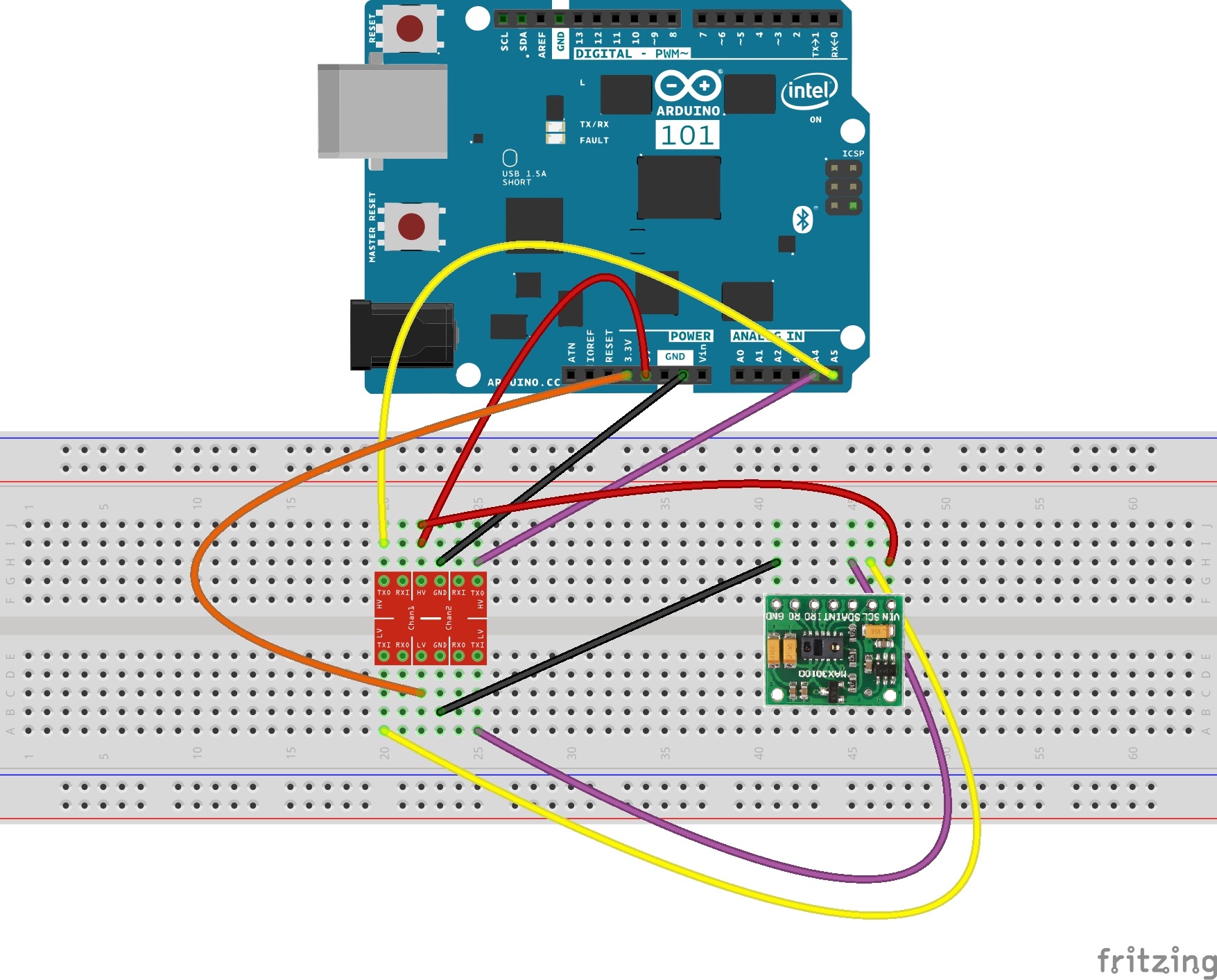
- at first we have to connect MAX30100 heart rate sensor to the Arduino 101 with I2C protocol. MAX30100 logic level is 3.3V, Arduino 101 works with both 5V and 3.3V. but Grove LCD works with 5V I2C protocol. so we need to convert the logic level between Arduino 101 and MAX30100. as we are using I2C protocol, the SCL & SDA cables from the MAX30100 goes to TXI of logic level converter, and the cables from the Arduino 101 goes to TXO of logic level converter. the HV will be connected to 5V , LV to 3.3V and GND to GND fo Arduino. then solder MAX30100 and a long wire together, now connect the other end of long wire to the breadboard. now you can use your sensor far from the main board!
- Step motor (28BYJ-48) will be connected to its driver (ULN2003) easily by thair sockets. the driver's VIN to 5V of Arduino, GND to GND, and IN 1,2,3,4 pins to digital pins 2,3,4,5 of Arduino.
- Buzzer socket will be connected to D8 of the shield.
- Touch button socket will be connected to D4 of the shield.
- The Grove LCD will be connected to the I2C socket of the shield.
For controlling the amount of drug that will be injected to patient's body. we use an step motor that works like an dialysis pump! this kind of pump works by pushing the liquid that is inside a hose by pressing it!
The code is commented and completely functional and i think it's easy to to be understood. but the highest and lowest heart are not constant for every one and you should change them to your specific heart rate.
#define LHB 30
#define HHB 100
now that every thing is ready we move the whole boarde and injection system neare to the patient's bed.


_baVEVgguW1.jpg?auto=compress%2Cformat&w=48&h=48&fit=fill&bg=ffffff)


_3u05Tpwasz.png?auto=compress%2Cformat&w=40&h=40&fit=fillmax&bg=fff&dpr=2)
Comments
Please log in or sign up to comment.