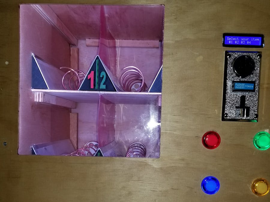
This project is a step by step build of a personal vending machine. The vending machine can be filled with your favorite snacks or could be brought to the office so you can share some treats with your team. Take a look and let me know your thoughts.
UPDATED CONTENT- Please check the bottom of this text (LED STRIP SECTION) to see the update. Code and circuit diagram was also added to the details so you can set it up also.
Building the Machine :
I will refer to the diagrams of the machine throughout this text so please refer to the diagrams for clarification/understanding.
The dimensions of the machine are 21"W x 18"D x 24 1/4"H (Box Dimensions)
2 panels 18"D x 23 3/4"H (Sides)
2 panels 21"W x 18"D (Top & Bottom)
2 panels 21"W x 24 1/4"H (Front & Back)
Divider wall is 18"D x 23 3/4"H
Internal Shelf is 13"W x 12"D (times 2, upper and lower shelf)
Shelves are 8” apart 13” wide 12” deep
Each blue block on the panels diagram is a ¾”W x ¾”H mounting point as deep as the panel
Assemble the box as shown in the diagram and here using the 3/4" blocking at each of the junction points. Take note that the sidewalls sit on top of the bottom plate and under the top plate. The perimeter walls should measure 21"W by 24 1/4"H.
The Divider wall needs to be setup before installing. Measure down from the top 16 1/4" and attach blocking there for bottom shelf. Measure down 8 1/4" from the top and attach blocking for top shelf. Complete these steps on the left wall (looking from the front of the machine) so you can attached the blocking for the top and bottom shelves.
**** Note the bottom shelf needs to be installed first otherwise securing to the blocking will be very difficult.
Once blocking is installed for the shelves use the 13" x 12" panels and install one on each set of blocking. This will automatically setup the divider wall in its proper place. Then secure blocking at the top and bottom of the right side of the divider wall. Then secure it to the top and bottom panel This will completely sure up your structure.
Install the back panel and get ready for the motor installs. Make sure you have the coil wheels printed so you can measure them and setup your drill holes. Measure the wheels and add 1/4" to the height so it it will leave room for the coil to spin. You may want to adjust this as needed depending on your material. Measure over 6 1/2" on the shelf to mark its middle. Measure over 3 1/4" to find the center of each shelf section. Use the height measurement you recorded moments ago to find the drill points. Drill a hole that will allow you to connect the wheel to the motor without the wheel shaft rubbing on the board. Finish mounting the motors and screwing in the fasteners.
Setting up the motor relay:
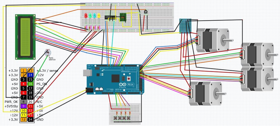
Connect the pins as follows. Use chip L293D (notch to the left) (In circuit diagram) so you can control the relay. This will allow you to connect the motors to power.
(Starting Left to Right)
Pin 1 connect to pin socket 10 on controller (In circuit diagram)
Pin2 connect to pin socket 9 on the controller (In circuit diagram)
Pin 3 connect to positive side of relay (with the 3 pins facing you, pin on left) (In circuit diagram)
Pin 4 connect to 12V ground on breadboard (In circuit diagram)
Pin 5 Not used (In circuit diagram)
Pin 6 connect to Ground side on relay (with the 3 pins facing you, pin on right) (In circuit diagram)
Pin 7 connect to pin socket 8 on controller (In circuit diagram)
Pin 8 connect to +12V on breadboard (In circuit diagram)
Connect middle pin on relay to +12V on breadboard (In circuit diagram)
Connect back right pin on relay (with the 3 pins facing you, pin in back on right) to the positive lead going to the motor drivers (In circuit diagram)
Screen & button installation: Screen - Pick a spot on the right side of the machine (looking at the machine from the front) and mark out the hole that needs to be made for the display portion of the screen (2.53937" x 0.5708661) Button - Pick a spot on the right side of the machine (looking at the machine from the front) and mark out the holes that need to be made for the 4 buttons. The holes needs to be 1.10236" if using the exact same button in the parts list. I like to use a drill bit smaller then needed and sand paper to bring it out to the needed size.
Keep in mind that you need to make sure that you have all of the connections in the exact same spots as in the diagram above. The LEDs shown in the diagram are the LEDs built into the push buttons. The diagrams show them separate but that is only for display and to make it easier to read the schematic.
Connect each motor to the driver provided with them. Then connect each driver to the controller using these steps:
Motor Setup:
Power should be connected to the 12V side of the breadboard. This power comes from the ATX power supply we will prep at the end. Then connect the 4 "in" pins on the driver to the controller. These pins are as follows
********* DO NOT CONNECT TO THE FIRST 2 PINS IN THIS BLOCK THEY ARE 5V PINS - NOT USED IN THIS PROJECT *********
Motor 1: Blue Pins 22, 24, 26, 28 (In circuit diagram)
Motor 2: Yellow Pins 23, 25, 27, 29 (In circuit diagram)
Motor 3: Green Pins 30, 32, 34, 36 (In circuit diagram)
Motor 4: Red Pins 31, 33, 35, 37 (In circuit diagram)
Button Connections:
Connect one side of Push Button 1 to power 5v, the other side to a grounded 220 resistor along with Analog Pin A0 (In circuit diagram)
Connect one side of Push Button 2 to power 5v, the other side to a grounded 220 resistor along with Analog Pin A1 (In circuit diagram)
Connect one side of Push Button 3 to power 5v, the other side to a grounded 220 resistor along with Analog Pin A2 (In circuit diagram)
Connect one side of Push Button 4 to power 5v, the other side to a grounded 220 resistor along with Analog Pin A3 (In circuit diagram)
LCD SCREEN:
Connect the screen to the 5v side of the breadboard for power and ground
Pins are as follows:
Pin 1: Connect to Ground(In circuit diagram)
Pin 2:Connect to 5v power (In circuit diagram)
Pin 3:Connect to adjustable potentiometer (Pictured below) Bottom left pin to ground, bottom right to power, and top pin to pin 3 on LCD (In circuit diagram, This is how you set the contrast on the LCD so text is crisp and clean)
Pin 4: First signal pin to controller pin socket 2 (In circuit diagram)
Pin 5: Connect to ground (In circuit diagram)
Pin 6: Second signal pin to controller pin socket 3 (In circuit diagram)
Pin 7: NOT USED
Pin 8: NOT USED
Pin 9: NOT USED
Pin 10: NOT USED
Pin 11: Third signal pin to controller pin socket 4 (In circuit diagram)
Pin 12: Fourth signal pin to controller pin socket 5 (In circuit diagram)
Pin 13: Fifth signal pin to controller pin socket 6 (In circuit diagram)
Pin 14: Sixth signal pin to controller pin socket 7 (In circuit diagram)
Pin 15: Connect to 5v power (In circuit diagram)
Pin 16: Connect to Ground (In circuit diagram)
ATX POWER SUPPLY:
Only cut the wires needed to power the device. The other wires are safer in the plastic connector and will allow you to use it for other projects if needed.
ATX Pins:
Cut and strip (Ground) black wire pin 3 and the (Signal) green wire pin 16. Attach these wires to a switch so you can turn on and off the machine (In circuit diagram)
Cut and strip (Ground) black wire pin 7 and (+12V) yellow wire pin 10. Attach these wires to the 12v side of the breadboard designated in yellow and black connections. (In circuit diagram)
Cut and strip (Ground) black wire pin 24 and (+12V) yellow wire pin 11. Attach these wires to a compatible connector to power the Arduino board (In circuit diagram)
Cut and strip (Ground) black wire pin 19 and (+5V) red wire pin 21. Attach these wires to the 5V side of the breadboard (In circuit diagram)
Shelf Dividers and Coils:
Here is how to setup your shelves and extruders.
Shelves - At the middle point 6 1/2" from the left side wall (looking at the machine from the front) or divider wall there should be a mark from the steps above. Use the flat metal and bend it into the top of a triangle. Looks just like this "^" This will serve as your middle divider. Center the triangle over the middle mark on the shelf. Repeat for the second shelf. Use hot glue to fasten in place. I put slides on the sides also but they are optional.
Coils - To create the coils first find a 1 1/2" tube. A pipe, caulk tube, spray paint can, or similar object will do. One trick is to take a rubber band and wrap it from top to bottom around the length of the tube. Trace the straight line down each side of the band on both sides of the tube. Once you have parallel lines down both sides use a tape measure to mark the next spots. Pick one side and measure in 1" and mark it, then measure 2" from there mark it and keep making 2" spaces all of the way down the tube. Now, on the other side of the tube mark only 2" intervals. Start making the coil on the 1" side of the tube and continue making your coil so it touches each mark on the both side of the tube. This will give you a 2" gap between the rungs. Should be large enough for most items. If you plan to use it for candy bard shorten the coil to 1" just reduce the formula above by half.
Connecting the coils to the 3D printed wheels. Keep in mind that there are some manufactured wheels that will work. Take a look on Amazon.
On the 1" side of the coil collapse this coil so it make a circle. Then shorten the diameter to slightly smaller then the wheel. Once the coil is ready fit it around the edge of the wheel. This should cause the coil to compress around the edge of the wheel and keep it from slipping. Once you are happy with the fit take a small dab of hot glue and put it on the wheel at the end of the coil to hold it in place.
LED Strip Lights:
Connect Positive lead to +12V pin on the 12V side of bread board. Connect the ground lead to the ground pin on the 12V side of the bread board (Not in diagram)
PLEASE ASK ALL OF THE QUESTIONS YOU HAVE SO I MAY ASSIST WITH UPDATE TO MAKE THIS THE EASIEST PROJECT EVER.


_wzec989qrF.jpg?auto=compress%2Cformat&w=48&h=48&fit=fill&bg=ffffff)


Comments
Please log in or sign up to comment.