


Hardware components | ||||||
 |
| × | 1 | |||
 |
| × | 1 | |||
| × | 1 | ||||
| × | 1 | ||||
| × | 1 | ||||
| × | 1 | ||||
| × | 1 | ||||
| × | 1 | ||||
| × | 1 | ||||
This project allows you to use a Pebble Smartwatch and a Sparkcore microcontroller to make a Smart Garage that can be opened and closed with the Pebble from anywhere that you have an internet connection. The Pebble application is written in Pebble.js and can execute an Ajax request when the watch buttons are pressed. The Sparkcore is a microcontroller similar to the Arduino but with onboard Wifi that has a RESTful interface so it can easily handle the Ajax request coming from the Pebble.
A more detailed writeup on this project with code, build instructions and wiring diagrams are available on my original blog post here:
http://contractorwolf.com/sparkcore-smart-garage/
Getting Started
I had previously done an IOT garage door opener with the Arduino and the CC3000 shield from Adafruit and it worked, but had issues maintaining a reliable connection without constant polling. That original project had some work done by Chad Stachowicz.
I decided to make a significant upgrade of that idea with my favorite new IOT device: the Sparkcore from http://spark.io/. The Sparkcore is perfect for this because it abstracts away the whole task of connection maintenance and allows you to focus on the code of your application. As long as it has power and proper credentials, it is always connected.
I added a nice I2C OLED from http://Wide.HK to display the status of the Garage Door and added an LCC120 Digital relay to emulate the garage door button being pressed. The power for the device comes from a USB power supply (from a phone) that I have plugged into the wall.
I switched the normal cyan breathing on the RGB LED to be an ultra dim green. It turned a red if the device lost cloud connectivity. I have only ever seen it turn red once when the router was being rebooted. The rest of the time it gently suggests that Wifi is working with a dim green, without becoming distracting.
I made a custom board for the Sparkcore that had spots to connect the OLED and the connections for the Reed Sensor and the digital relay to operate as the “button press” on the on the original button. The Reed Sensor are those window sensors that used to signal when a window has been open like these below.
I wired a line from my SmartGarage to the door, so that the Sparkcore would always know if the door was open or closed. The Reed Switch is wired from the 3.3v line to an analog input pin and set that pin to be a digital input. That way I can ask the pin if it was open or closed (1 or 0).
The line went to an unoccupied spot on the door. I used a glue gun to attach both parts of the Reed Switch so that it was held tight but would be easy enough to remove later (see second pic above).
The board (think “shield” for the Sparkcore), was made from a simple proto-board with the traces from connecting square pads with solder on the board to make traces. The Sparkcore plugs right into the 2 rows of headers. You can see in the diagram that it can be done as a single-sided PCB. I worked it out on paper until I could get something that was single-sided.
The digital relay allows me to emulate the button being pressed without connecting the Sparkcore directly to the garage door circuitry. I could have used an opto-isolator just as well, but I had the digital relay already, so I used that. Applying power to 2 pins on the relay connects the two pins that are attached to the garage door button. The other two screw terminals are used to attach the Reed Switch to the A0 pin (used as a digital input) and 3v.
What I am connecting in these pictures is the Sparkcore to the OLED screen, the LCC 120 digital relay, and a bunch of connectors for the Sensors and the LED’s. If you are making one yourself the diagram lists all of the pins of each of the components. I also made sure to color code the wires as best as possible. Using the 3 images above you should be able to understand the wiring and the lines to solder.
Operation of the SmartGarage with Pebble Steel
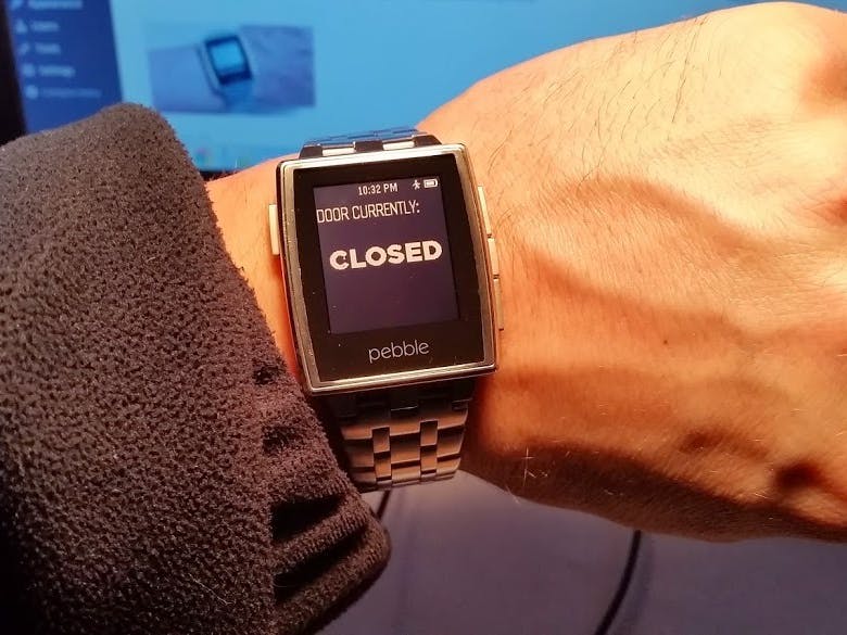
To operate it remotely and check on its status I use my Pebble Steel smartwatch. I wrote a quick application in javascript (called SmartGarage) that allows me to query the status of the door (using the RESTful services of the Sparkcore). Because the Pebble can run Javascript applications it can easily make AJAX requests when buttons are pressed.
When I hit the middle button it sends a secure command to the Sparkcore and asks the doors status. It allows you to press a button to open (top) and close it (bottom). The Pebble app and the Sparkcore are tied by the Device ID and the Auth Token located in the Pebble app, so they have a one-to-one relationship.
A Pebble Smartwatch is not really a requirement for this project. You can execute the “door open” command using a web application just as easily. The RESTful interface means that any device or application (such as a smartphone app) that can execute HTTP request can operate the garage door. I just thought that the Pebble was a nice add on and since I already had one I wanted to see if it could be integrated into this application.
The Code for the Sparkcore and the Pebble Smartwatch
The Github Repo for the Sparkcore to run the SmartGarage module is here:
The code for the Pebble.js app that will run on the Pebble Smartwatch. You only need to switch the Device ID and Access Token to match your account. It can be easily deployed on CloudPebble.com is available here:
The code is open source and freely available to all. You can modify it as much as you need to fit your project or design. Just give me some attribution if you use it and please send me a link to your project. Send me a pull request on GitHub if you find something that I forgot that you think should be included.
3D Printed Case for the Sparkcore SmartGarage
I designed a three part 3D printed case for the SmartGarage in SketchUp so anyone can 3D print the parts for this project. The first part is the main case that holds the circuit, the OLED and the Sparkcore. The PCB slides in and locks in place with the USB port pointing down. The screen then mounts on top of that. The front panel slides its tabs under the section that holds the OLED and locks in place. The wall mount should be attached with drywall anchors and then the main case with the front panel installed should both be slid into the wall mount.
I have the SketchUp file that contains all 3 parts shared on my Google Drive here:
SmartGarage Case SKP file (SketchUp Design file)
If you need just the individual parts for printing I also have the STL files available for download as well:
If you are trying this project yourself simply leave any questions you have on my blog or in the comments below. You can also contact me on Google Plus here: http://google.com/+jameswolf


Comments
Please log in or sign up to comment.