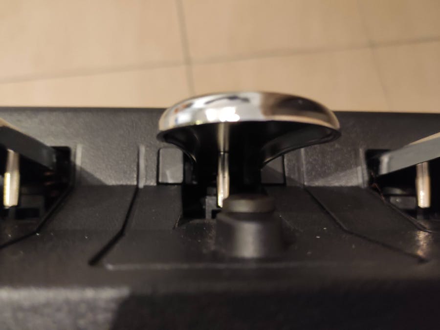
Here is a way to convert a (faulty or not) Kawai F-30 pedal (or identical Stugiologic/Fatar unit) into a standalone USB triple continuous pedal (i.e. all 3 pedals send continuous values). Since this mod actually enhances the pedal's operation it is not only for faulty ones and can even be used by non Kawai owners that just want a USB triple pedal. The mod is based on an old idea by John O'Flaherty that I have built upon. I am using an Arduino Micro and 3 Linear (analog) Hall effect sensors to get analog signals from all pedals with strategically placed magnets.
Pros:
1. No soldering needed - no electronics experience needed
2. Does not interfere with the pedal's original operation and is completely reversible. It is also seamless/invisible with the exception of the extra USB cable that comes out of the pedal.
3. It is plug and play - the pedal is recognised as a regular MIDI device just as your keyboard
4. It is fully configurable, each of the 3 pedals can send any controller/mono aftertouch/pitch bend up/down
5. Curves can be defined for each pedal independently and work on raw input values to avoid losing resolution (as with software curves)
6. It is auto-calibrated
7. Relatively cheap solution: under 30 EUR with a genuine Arduino and if you go with clones you can go even lower.
Caveats:
1. You need to install Arduino IDE (just a small application really)
2. Configuration changes need modification and reupload of code - no controller application available. But this is a breeze with Arduino IDE and the changes are just changes in text
3. Since the pedal becomes an independent MIDI device you need to know how to route it in our apps and DAW. I have tested and it works perfectly along with my VPC1 using Addictive Keys, Ravenscroft VI, Pianoteq, Garritan CFX, Kontakt (Noire) and Reaper and should work everywhere provided multiple input MIDI devices are allowed.
Steps to recreate:Step 1:Insert the Arduino to the breadboard accross the middle gap so as to leave 4 free holes on one side and 1 on the other. Each pin should be inserted, press firmly so as to go as far in as possible.
Prepare the sensors. Connect the sensors to the female side of the jumper wires, use a black wire for the left (-) connectors, a red wire for the middle connectors and a different color for each of the right connectors (S) - I have selected Orange, Yellow and Green respectively. Insert firmly.
Disconnect and disassemble the pedal. Remove the bottom four screews, then remove the 2 inside ones (left and right). Nudge the pedals while holding the enclosure (upside down) to separate the enclosure from the innards. Notice the bar running in the middle of the pedal that is used to keep the innards in place and remember its original orientation.
Step 4:With the removed pedal structure upside down pass all the cables from the sensors one by one through the hole shown in the picture below:
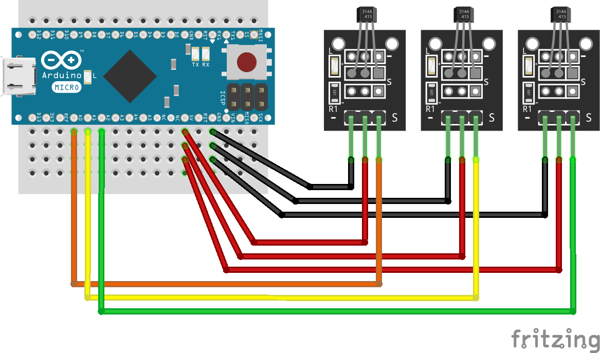
Connect the male cables to the breadboard (see also attached schematic). You might need a magnifying glass (I did). Connect as follows:
3 Black cables go to the 3 pins on the column immediately beneath Arduino's GND (ground) pin
3 Red cables go to the 3 pins on the column immediately beneath Arduino's 5V pin. Notice there is one empty column separating the red from the black wires.
The three colored connectors should go to the pins directly underneath the A0, A1 and A2 pins of the Arduino respectively. Take notes of the color-pin correspondence for later, in my case A0:Orange, A1: Yellow, A2: Green.
Once all connections are finalized, you can use tie wraps to secure all wires together and avoid disconnections, I have added one just above the Arduino and one on the side of the sensors. You can now connect the USB cable to the Arduino.
Step 7:Fit the Arduino upside down in the space between the left and center pedals. The USB cable should pass behind at the back of the pedal as the normal cable of the pedal. The fit might be a little tight, depending on the micro-USB side of the cable you have used, but it will evetually find its way once you reinsert the pedal structure into the enclosure.
While upside down, you have to secure the 3 sensors on the horizontal plastic bar with tie raps. The sensors are placed upside down with their up side facing the pedals and not the base. Notice that since you are seing the pedal upside down the order of the pedals is reversed. A0(orange) should go to the left pedal as seen when the pedal is in its normal upward position (i.e the Soft/Una Corda pedal), A1(yellow) to the middle pedal (sostenuto) and A2 to the right pedal (Hold). Notice the three pairs of indentations on the bar, the tie wraps will need to pass through them and into the respective holes of each sensor. Take care so that the buckles of the tie wraps do not protrude but end up on the side of the bar. Trim the excess plastic after the buckle once finished. The sensors should be stable. The actual sensing part is the little chip at the end of the sensors, this should end up above the square holes of each pedal.
You can optionally use small pieces of foamed plastic (for example the one included in your arduinos package) above the sensor connections to keep them in place once the base is screwed in. On top of that cover the sensors with insulation tape to insulate the sensors from the metal base.
Once sensors have been placed, you can click the bar into place and screw the 2 internal screws so that the sensors take their final positions.
Use a mobile app to determine the south poles of each of the three magnets. Here is an example app: https://totalelement.com/pages/magnetic-pole-detector-android-ios-app#:~:text=Quickly%20and%20easily%20identify%20the, output%20a%20north%2Fsouth%20reading.
Position the magnets underneath the sensors with South pole facing the sensor. Finetune position by pressing each pedal fully so that the magnet is immediately underneath the sensor chip but not touching. Magnets will sit on the metal pedals but if you want to avoid any potential movement you can secure with glue pads around the magnet.
Screw the base back. Hardware part is finished!
Step 13:Install arduino IDE for your platform:
https://www.arduino.cc/en/software
Step 14:Plug in the USB cable to your computer. Run Arduino IDE. Within Tools menu select Board: Arduino Micro and Port: the port that will have auto detected your arduino.
Step 15:Create a new sketch (File->New) copy the code from this instructable and paste it to your new sketch (overwriting the existing text). File->Save to save with your desired name.
Step 16:Sketch->Upload. This will compile and upload the code to your arduino. If done succesfully, you will be able to find the Arduino Micro as a MIDI device in your DAW and music applications. You will then have to select it as MIDI input and route it along with your keyboard in order to merge the pedal input with it.
Important note: The first time you depress each pedal after connection/code upload it will auto-calibrate. For that reason the value will go directly to 127 the first time you press it. After that it will behave as expected.
Advanced Notes:The first part of the code contains user setup values. They are self descriptive and there are comments explaining their function. You can control what messages are output, their channels and also adjust curves manually. For each change you need to reupload the code (step 16).
The unipolar setup of Hall Effect sensors does not yield linear results. Input can be approximated with a quadratic. The default curves take care of that and you can even adjust them to your liking.
Curves although in the 0..127 range work on input domain hence there is no loss of resolution. Raw value resolution on my setup is around 300, far better than MIDI's 128. Resolution can vary between sensors and magnets.
You can change the name of the MIDI device by changing the name of Arduino Micro in the boards.txt file and reuploading the code. It is a little difficult to locate and edit this file but there is information online for each platform. In windows it should be in (change your username accordingly): C:\Users\username\AppData\Local\Arduino15\packages\arduino\hardware\avr\


_PnKPri8a6q.jpg?auto=compress%2Cformat&w=48&h=48&fit=fill&bg=ffffff)


Comments
Please log in or sign up to comment.