


Hardware components | ||||||
 |
| × | 1 | |||
| × | 1 | ||||
 |
| × | 2 | |||
Software apps and online services | ||||||
 |
| |||||
Hand tools and fabrication machines | ||||||
 |
| |||||
 |
| |||||
 |
| |||||
| ||||||
 |
| |||||
This project started with receiving the robot as part of a class at the University of Texas at Dallas. Throughout the class, we learned how to program the various parts of the robot, including LEDs, motors, bumper switches, timers, and interrupts.
At the end of the class, the group project required us to program the robot to find the treasure in a black and white line maze with 90-degree turns and no loops. The treasure is denoted by 3 parallel black lines with white gaps between them. The robot also needed to reverse and turn around if it hit something, and it needed to use LEDs to indicate various things (turning, discovery of the treasure, and bumping into something). We were the only successful group, and we have gone even further by programming the robot to remember the shortest path to solve the line maze after it has solved the maze once.
VideosVideo 1 is an introduction to the robot for people who don't want to read all the text below. (6 minutes, 33 seconds)
Video 2 shows the robot solving a maze from 2 different starting locations and also shows the robot demonstrating the shortest path to the treasure from both locations. (3 minutes, 35 seconds)
Video 3 shows the same things as video 2 but without any commentary and explanations. (1 minute, 25 seconds)
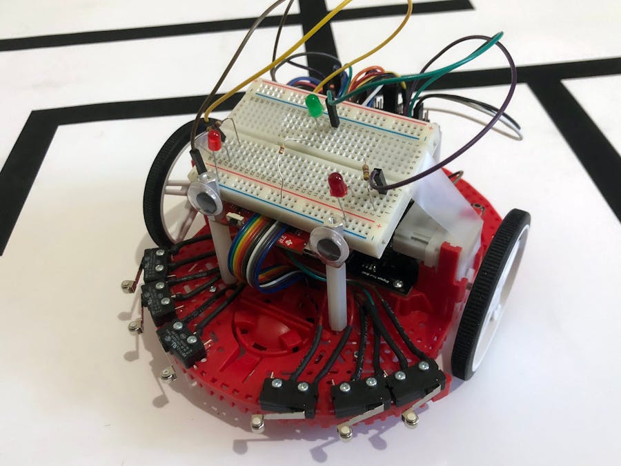
Building the RobotTo build the robot, we simply followed the TI RSLK Basic Kit building instructions. We have attached them in the Schematics section of this post. The only change we made to the instructions was that we did not cut any connections on the PCB. The instructions provided by TI will get you through everything except building the breadboard and placing the breadboard on top of the robot.
Before placing the breadboard on top of the robot, follow the breadboard schematic in the Schematics section of this post to attach the LEDs to it. This will be hard to do later because the wire connections will be under the breadboard. Then, to attach the breadboard to the robot, we used Scotch tape. You could use anything you'd like, including the screws provided in the kit, but tape was cheap and much easier than trying to screw through a breadboard.
Programming the RobotTo program the robot, it must be plugged into a USB port on your computer and the batteries must be turned off with the switch on the motor board (black board). Then, with the downloadable project open in Code Composer Studio (CCS), click the Debug button. This compiles and loads the code onto the robot. Once CCS has finished loading the code, it'll halt the robot and wait for you to press the yellow play button to debug the robot. You can, or you can press the red stop button to use the robot without being plugged in.
Operating the RobotTurning on the robot without USB power: Disconnect from USB and make sure there are batteries in the robot. Plug in the 2 wires shown above if you unplugged them earlier, and then slide the power switch on the motor board (black board) near the left wheel to the on position.
Left Launchpad button: Tells the robot to solve a new maze or stop whatever it's doing. Acts as a toggle button.
Right Launchpad button: Tells the robot to show the shortest path it has found. If the maze wasn't fully solved, it will show as much of the maze as it knows so far.
Debugging the robot with USB: If you want to see console output while using the robot, make sure you have a long enough micro USB cable for the robot to roam around; only a short one comes in the kit. Disconnect the 2 power and ground wires mentioned toward the end of TI's build instructions attached below (and pictured above). Plug the robot into your computer with USB, and turn on the motors by sliding the power switch on the motor board to the on position. It is important to not run the motors from USB because they behave differently than they do with battery power. That is why we disconnect those 2 wires and turn on the batteries.
Turning off the robot: Move the motor board (black board) power switch to the off position. Then press the power button just next to the switch to turn off the robot.
The Overall AlgorithmThe robot uses a state machine with 4 possible states: stopped, running, win, and solutioning.
- Stopped state: When the robot is turned on or if the user stops the robot in the middle of solving the maze or showing the solution.
- Running state: When it is solving a new maze.
- Win state: If it has found the treasure in the maze.
- Solutioning state: When the robot is showing the shortest path (the solution) to solve the maze.
The robot uses the SysTick timer to periodically read the line sensors using interrupts. The line sensors are unable to send interrupts themselves, so this is the most efficient alternative.
When the robot first enters the main() function, it initializes everything it needs to initialize: its state, clock speed, motors, bumpers, line sensor, on-board buttons, on-board LEDs, breadboard LEDs, timer A0, SysTick timer, and interrupts. It then goes into a while-loop that runs forever.
Inside this while-loop, the robot saves the value of the line sensors to a temporary variable that it can use in case the SysTick timer interrupt activates mid-loop and changes the value of the global line sensors variable. It then acts differently depending on which state it is in.
If the robot is in the stopped or win state, the SysTick timer gets its interrupts disabled, and then the robot waits for an interrupt, which would come from the bumper switches, one of the buttons on the Launchpad board, or from timer A0 (which is discussed later and used for the LEDs on the breadboard). Setting the robot to wait for an interrupt puts it in low power mode so it doesn't waste power.
If the robot is in the running state, the robot solves the maze. The details of this algorithm are explained in the below section "The Maze-Solving Algorithm".
If the robot is in the solutioning state, the robot shows the shortest path to solve the maze. The details of this algorithm are explained in the below section "The Shortest Path Algorithm".
Logic to Find the Shortest PathWhile the robot is following the algorithm in the below section "The Maze-Solving Algorithm", it also needs to store the shortest path to solve the maze it is solving. To do this, an array is used. Every time the robot makes a turn at an intersection (not just a turn where it had no other choice) or makes a u-turn, it stores that turn in the array. Then, if the last turn was not a u-turn, it checks to see if the last 3 turns can be simplified into something else.
For example, the robot making a left, then a u-turn, and then a left can be simplified to just going straight at that intersection. Because it turned around after going left, clearly that original left turn was wrong.
Here are the patterns that can be simplified. 'L' = left, 'R' = right, 'S' = straight, and 'U' = u-turn.
- SUL -> R
- LUL -> S
- RUL -> U
- LUS -> R
This algorithm runs when the robot is solving a new maze. It is made of multiple if-else-if-statements, only 1 of which executes. The if-statements follow a left-hand bias rule, meaning the robot always take the left-most path it can possibly take.
To start, if the line sensors read all white, meaning the robot is not on a line, it probably just ran off the line. The robot thus turns around and re-reads the line sensors to get an updated value. It also adds a 'U' to signal a u-turn in the shortest path array.
If all the sensors are black, the robot is at a T-intersection or 4-way intersection. Because the robot is left-hand biased, it takes the left path, re-reads the line sensors to get an updated value, and stores an 'L' in the shortest path array. Before making the left turn, the robot moves forward half a car so that the wheels are aligned with the intersection. It also keeps the left LED on the breadboard on while turning left.
If the robot has found the treasure, it moves forward a tiny bit and re-checks to make sure it really found the treasure. If it did, the robot enters the win state, stops the motors, and sets up timer A0 to flash the LEDs on the breadboard on top of the robot.
If there's a left turn, the robot moves forward half a car to see if it's an intersection or just a turn. It then turns left with the left LED on the breadboard turned on, and it also adds an 'L' to the shortest path array if it is an intersection and not just a turn.
If there's a right turn, the robot first moves forward a tiny bit and re-reads the line sensors to make sure it's a right turn and that left is not an option. If left is not an option, it then moves forward the remaining half of the car and checks if straight is an option. It then either goes straight or right. If it went straight, it saved an 'S' into the shortest path array. If it went right, it turned on its right breadboard LED for the turn.
The next else-if-statements were used to simply follow a straight line because none of the other special conditions were true. To do this, it finds the outer-most line sensor that is on and corrects accordingly. For example, if the left-most line sensor is sensing black, the robot should correct by turning left a significant amount while also going straight.
The Shortest Path AlgorithmThis algorithm runs when the robot is showing the shortest path through an already solved maze. Just like the maze-solving algorithm, it is made of multiple if-else-if statements, only 1 of which executes each time the while-loop runs.
To start, if the robot's first turn is to make a u-turn, it moves forward 1 car length and then turns around. It needs to move forward first so that the line sensors are in a good spot after it turns around.
If the robot has shown everything it's solved in the maze so far but still hasn't found the treasure, the robot switches to the running state and starts solving the maze.
If the robot has found the treasure, it acts exactly as it does in the maze-solving algorithm. It moves forward a tiny bit and re-checks to make sure it really found the treasure. If it did, the robot enters the win state, stops the motors, and sets up timer A0 to flash the LEDs on the breadboard on top of the robot.
If there's a left and/or right turn available ahead, meaning there's a potential intersection ahead, the robot first moves forward half a car and checks if straight is an option. It then uses it's knowledge of availability for left, straight, and right to determine if this is an intersection or just a turn. If it's just a turn, it follows the turn. If it's an intersection, it acts according to what the shortest path array tells it to do.
Finally, if none of the above if-statements were true, the robot simply follows the line the same way it does in the maze-solving algorithm.
Mazes with LoopsOur code enables the robot to solve mazes with loops and also display the path it discovered to get to the treasure. However, it will not necessarily find the shortest path through such a maze because loops allow for multiple paths to the treasure.
To modify the algorithm to find the shortest path with loops, the robot would need to track distance or time as it moves so it can identify which intersections it has visited and which directions it has traveled from each intersection. It would also need to travel along every line in the maze so it can be sure it has found the shortest path.
Other Miscellaneous AlgorithmsSysTick Timer/Line Sensors: The SysTick timer is set up to send an interrupt every 0.025 seconds, at which time the robot will read the 8 line sensors. To read the line sensors, the code charges up each sensor's capacitor with an LED for 10µs. Next, it switches the line sensors to be inputs and discharges the capacitors for 800µs. The digital value of each sensor is then read. Finally, the LED is turned off. This algorithm works because the capacitor in each line sensor discharges at a different rate if it is on black versus white paper.
Timer A0/LED Flashing: Timer A0 is initialized when the robot is turned on but isn't started until 1 or more LEDs on the breadboard on top of the robot need to start flashing. It then handles flashing the appropriate LED(s) by using interrupts to call the function provided to it when it was last started. Because timer A0 is only a 16-bit timer, there is also a counter used by the timer so that the function is only called every 50 interrupts instead of every interrupt.
Motors: The motors are run using PWM (pulse width modulation). To make the wheels spin faster, they are given a digital 1 value for a higher percentage of time (a few microseconds per period). When the motors need to do something, they are given a direction and prevented from sleeping. Then they are given the appropriate PWM signal based on how fast they need to go.
Bumper Switches: The bumper switches use active-low logic with internal pull-up resistors on the Launchpad board. When a bumper switch is hit, an interrupt occurs making the robot turn on the green LED, reverse, turn around 180 degrees, and then continue solving the maze. It also adds a 'U' to the shortest path array.
Start/Stop Buttons: There are left and right buttons on the Launchpad board. Their functions are described in the above section "Operating the Robot". Each button sends an interrupt when it is released, not when it is pressed. This ensures the robot does not suddenly start moving when the user is still pressing a button.
Checking for Treasure: As part of the algorithms that solve the maze and show the shortest path, the robot continually checks to see if it has found the treasure. It detects if it has found the treasure by looking for a black sensor, followed by a white sensor, followed by another black sensor. There can be any number of sensors that are black and white as long as the black-to-white and white-to-black transitions are there. It does not check for black-white-black-white-black, even though that is what the treasure looks like, because that would require the robot to be well-centered, thus making it unreliable. We also never got false positives with the black-white-black algorithm and the double-checking for the win condition described in the "The Maze-Solving Algorithm" section above.
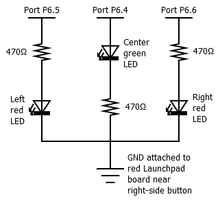
Top Breadboard Schematic with the 3 LEDs

Christopher Andrews


Comments