With the onset of the green revolution, energy systems are moving towards adopting 'greener' energy sources. However, current incentives for the increased adoption of sustainable technologies in the domestic setting, e.g. solar power, have not provided the impetus for global adoption. The major concerns for consumers involve financial stability, future microgrid integration and forecasting. An all-in-one solution, which can: monitor environmental conditions, record performance, forecast future energy production and allows users to 'trade' energy is needed.
Etron-V allows consumers to monitor their own renewable energy sources- namely solar panels- and integrate them with their local microgrid system. The system can log environmental conditions (i.e. daily sunlight and cloud cover) using both sensors and computer vision. The environmental data will be analysed and used to inform regression models for future forecasting. The system uses WiFi to send consumption alerts to users. Data can be written to the onboard sd card for future auditing. Moreover, Etron-V prepares users to integrate into upcoming microgrid systems. The device further communicates with a mobile app, where energy prices are dependent on community demand and supply. The app provides the potential for users to sell their own renewable energy to the grid or other users.
Section 1: The Design ProcessStep 1: Human Centred Design and Design ThinkingThe role of human-centred design in the world of sustainable technology development is becoming more widespread. Originally designed for creating effective solutions for developing countries, the process highlights three key aspects:
- User Desirability
- Technology Feasibility
- Business viability
Within our project as embedded energy storage and microgrids continue to be developed, our solution should be economically viable, desirable to current and future consumers, whilst also remaining technically compatible with future technologies. We can asses these factors mainly through focus groups and questionnaires.
Step 2: Design SpecificationThe design specification outlines all of the required features for a project. The aim is to keep them realistic and tangible.
Step 3: Initial IdeasCreating initial ideas via brainstorming is vital in ensuring successful designs are synthesised.
Step 4: Focus Groups and QuestionnairesThe spresense is a versatile board with great support for computer vision, audio, and has an in-built GPS and SD card reader. Familiarise yourself with the pinout before we start to install libraries.
Step 7: Installing Spresense LibrariesLoad up the Arduino IDE and choose File--> Preferences.
Under the additional boards manager URLs add: ttps://github.com/sonydevworld/spresense-arduino-compatible/releases/download/generic/package_spresense_index.json
Locate tools--> boards --> boards manager (note: I only have the spresense boards dropdown as I have already installed the packages).
Search for spresense board and install. You are now ready to start tinkering with the Spresense.
Step 8: DHT11 Humidity and Temperature SensorThe first stage is to add the DHT11 (Humidity and Temp) Sensor. For this example I have a 3 pin version. You need to install the dht.h library, which I have uploaded to my GitHub as a.zip folder
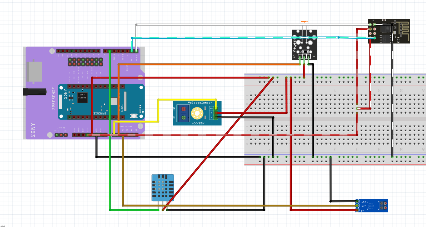
The next stage is to connect the DHT11 Sensor to the Spresense. You can directly connect the power (gnd and vout) pins without a breaboard. However, as we increase the no. of sensors it becomes a necessary aspect of the project.
Familiarise yourself with breaboards BEFORE you start connecting components together. There are many good simulation tools (e.g. circuit io or Tinker Circuits).
We can then run the following code to test the sensor.
#include <dht.h>


#define DHT_PIN 6 // DHT11 Sensor Digital Pin

dht DHT;

enum: byte {IDLE,DHT11ALERT} currentState= IDLE;


void setup() {
   Serial.begin(9600);
  delay(500);//Delay to let system boot
  Serial.println("DHT11 Humidity & temperature Sensor\n\n");
  delay(1000);//Wait before accessing Sensor

}

void loop() {
  switch (currentState){
    case IDLE:
    DHT.read11(DHT_PIN);

    Serial.print("Current humidity = ");
    Serial.print(DHT.humidity);
    Serial.print("%  ");
    Serial.print("temperature = ");
    Serial.print(DHT.temperature);
    Serial.println("C  ");
    delay (5000);

    if (DHT.humidity >60){
      Serial.println("High Humidity");
      currentState = DHT11ALERT;


    }
    break;

    case DHT11ALERT:
    DHT.read11(dht_apin);
    Serial.println("Too Hot");
    Serial.println(DHT.humidity);
    delay(5000);
    if(DHT.humidity <55){
    currentState= IDLE;
    }
    break;

  }


}
The code sets up the sensor, and takes readings every 5 seconds. If a reading is past a certain threshold (e..g 60 in this case), then it switches to an alert and returns to relaying sensor values to the serial monitor.
If the code does not work, these are the possible reasons why:
1) Wrong DHT library is installed- check your own sensor instructions and make sure you have not installed a similar library e.g. DHT.h not dht.h (notice the difference).
2) Wrong digital pin attached- carefully check the pinout provided in an earlier step
3) Using analogue pin as a digital pin: the spresense does not support this functionality. Use a digital pin instead.
4) Incorrect baude rate- easily diagnosed if you have weird characters appearing on the serial monitor
Step 9: Light SensorThe light sensor used is the KY-018- a simple photoresistor based voltage divider (see the SMD resistor in the circuit diagram). The setup can easily be made using a normal resistor and photoresistor if you do not have a sensor available.
Connect the sensor as follows:
#define LIGHT_PIN A1
int lightSensorValue;

void setup() {
  pinMode(Sensor,INPUT);
  Serial.begin(115200);
  // put your setup code here, to run once:

}

void loop() {
  sensorValue=analogRead(LIGHT_PIN);

  Serial.println(lightSensorValue,DEC);
  delay(5000);
}
The code simply serial prints all of the sensor readings. Note if the readings are VERY low (e.g. 0 to 10) even in varying light conditions, there is something wrong.
Troubleshooting:
1) Check analog pin connection- you should not use a digital pin in this case
2) Check wiring and connections
3) Incorrect baude rate- easily diagnosed if you have weird characters appearing on the serial monitor
Step 10: Voltage SensorThe voltage sensor is again a simplistic module, which uses a basic potential divider circuit to determine voltage. The output of the sensor is an ADC value - simply a ratio of the load. We need to be able to convert this to volts, which we can do using the potential divider formula:
V= R1/R1 + R2
Wire the sensor up as follows:
#define VOLTAGE_PIN A0 //Voltage Sensor Analog Pin
// VOLTAGE SENSOR
float adcVoltage = 0.0;
float inVoltage = 0.0;
float R1 = 30000.0;
float R2 = 7500.0;
float refVoltage = 5.0;
int adcValue = 0;

void setup(){
   // Setup Serial Monitor
   Serial.begin(9600);
   Serial.println("DC Voltmeter Test");
}
void loop() {

adcValue = analogRead(VOLTAGE_PIN);


        adcVoltage  = (adcValue * refVoltage) / 1024.0;  //Sensor reports ratiometric value which ranges between 5 to 1024 for anything less than 5V.


        inVoltage = adcVoltage / (R2 / (R1 + R2)); //Potential Divider Calculation


        Serial.print("Input Voltage = "); //Prints values to serial monitor
        Serial.println(inVoltage, 2);

}
The code above takes care of these conversions for us. We also need to attach probes to our terminal screws. You can test out the code on a battery
The GNSS module is built in the spresense. The following script will help you connect to the satellites for the first time and help debug any issues.
#include <GNSS.h>
#include <Arduino.h>

static SpGnss Gnss;
SpGnssTime current_time;


void setup() {
  /* Setup serial output for printing. */
  Serial.begin(115200);

  /* Initialize GNSS. */
  Gnss.begin();
  Gnss.select(GPS);
  double lat = 51.593830;
  double lon = -0.264000;
  Gnss.start(HOT_START);


}

void loop()
{
  /* Wait for an update. */
  if (Gnss.waitUpdate(-1))
  {
    /* Get navigation data. */
    SpNavData NavData;
    Gnss.getNavData(&NavData);

    /* Print position and satellite count. */
    Serial.print("Lat=");
    Serial.print(NavData.latitude, 6);
    Serial.print(", Lon=");
    Serial.print(NavData.longitude, 6);
    Serial.print(", Satellites=");
    Serial.print(NavData.numSatellites);
    Serial.print(",Time=");
    Serial.print(current_time.hour);
}
}
We can also make use of GPS time as an accurate clock for the board. This is very useful for our "black box" system, where we will store sd card data (next step). The first time can take a prolonged period to connect (min of 4 satellites needed)- so make sure you are outdoors to ensure a good connection.
If you are struggling to make a connection, you can try other protocols (define in setup):
void setup() {
Gnss.begin();
Gnss.select(GLONASS);
Gnss.start();
}#include <GNSS.h>
#include <Arduino.h>
#include <SDHCI.h>
#include <File.h>
static SpGnss Gnss;
SpGnssTime current_time;
SDClass SD; /**< SDClass object */
File myFile;
void setup() {
/* Setup serial output for printing. */
Serial.begin(115200);
/* Initialize GNSS. */
Gnss.begin();
Gnss.select(GPS);
double lat = 51.593830;
double lon = -0.264000;
Gnss.start(HOT_START);
Serial.print("Insert SD card.");
while (!SD.begin()) {
; /* wait until SD card is mounted. */
}
/* Create a new directory */
SD.mkdir("dir/");
/* Open the file. Note that only one file can be open at a time,
so you have to close this one before opening another. */
myFile = SD.open("dir/test.txt", FILE_WRITE);
}
void loop()
{
/* Wait for an update. */
if (Gnss.waitUpdate(-1))
{
/* Get navigation data. */
SpNavData NavData;
Gnss.getNavData(&NavData);
/* Print position and satellite count. */
Serial.print("Lat=");
Serial.print(NavData.latitude, 6);
Serial.print(", Lon=");
Serial.print(NavData.longitude, 6);
Serial.print(", Satellites=");
Serial.print(NavData.numSatellites);
Serial.print(",Time=");
Serial.print(current_time.hour);
Serial.println(""); if (myFile) {
Serial.print("Writing to test.txt...");
myFile.println(NavData.numSatellites);
/* Close the file */
myFile.close();
Serial.println("done.");
} else {
/* If the file didn't open, print an error */
Serial.println("error opening test.txt");
}
/* Re-open the file for reading */
myFile = SD.open("dir/test.txt");
if (myFile) {
Serial.println("test.txt:");
/* Read from the file until there's nothing else in it */
while (myFile.available()) {
Serial.write(myFile.read());
}
/* Close the file */
myFile.close();
} else {
/* If the file didn't open, print an error */
Serial.println("error opening test.txt");
}
delay(5000);
}
}The code adds to the previous GNSS example by storing the number of satellites onto a text file.
Step 14: Setting up Audio + Adding Audio AlertsOnce you have the SD Card functionality working, it is time to add AUDIO alerts ! To setup MP3 audio playing use the audio example from spresense (examples- audio- player).
Add wiring to the audio aux cable and connect to a speaker:
Then run the audio alerts programme from the GitHub !
Troubleshooting:
1) Check naming of sound file
2) Check speaker has adequate amplifier (use headphones to test !)
3) Check aux cable/ connections
Section 3: Assembling SubsystemsStep 15: Adding Wifi To SpresenseUse the main code in my GitHub repo to add wifi functionality !
It's important to get the tx and rx pins in the correct orientation ! If the ESP-01 does not work you may need to flash it (see here: https://www.hackster.io/pratikdesai/flash-firmware-on-esp8266-esp-01-module-e1f758)
Also be wary about using 3.3V ! The ESP-8266 will be damaged if you use 5v. If you are set on using 5V then use a level converter !
Step 16: Connecting to ThingSpeakThe first stage is to setup your account and channel on ThingSpeak.
Then create a new channel, adding all the necessary fields and saving the channel.
Navigate to API Keys and find your WRITE key.
Add your WRITE key to the Spresense code on the IDE.
You should now see data being sent to ThingSpeak !
Troubleshooting:
1) Make sure its the write key - pun intended :)
2) Generate new key and retry
3) Check IDE code and ensure code is unchanged.
Demos (Videos and Images):All videos of the demos can be accessed here: https://drive.google.com/drive/folders/1v3AJ9VFKJZr7AJ-_uWGFa2zt_W8CGFDi?usp=sharing


Comments
Please log in or sign up to comment.