


Hardware components | ||||||
 |
| × | 1 | |||
| × | 1 | ||||
| × | 2 | ||||
| × | 1 | ||||
| × | 1 | ||||
| × | 1 | ||||
 |
| × | 1 | |||
| × | 1 | ||||
| × | 1 | ||||
| × | 1 | ||||
| × | 3 | ||||
| × | 1 | ||||
Software apps and online services | ||||||
| ||||||
| ||||||
Hand tools and fabrication machines | ||||||
 |
| |||||
 |
| |||||
As an avid music listener, I love listening to music in my room or when studying. I often use Spotify's built-in full screen feature to set an ambiance but I always wished that there was a more immersive option. I enjoy the retro style of LED matrices and decided to create a desktop Spotify viewer with a real-time visualizer. After discovering that "Ticker", a previous project, had created a desktop widget box with the option to add more widgets, I decided to use Ticker as a foundation and build off of it to create the ultimate Spotify box, and thus Spotibox emerged.
FeaturesThe Spotibox widget shows the album art, track title and artist, and a real-time visualizer. The currently playing song info automatically updates and the playback can be paused, played, skipped, and reversed using the action button on the box. The visualizer uses the magnitude of each pitch/note, derived from the Fast Fourier Transform (FFT) of raw song data, at each time point to display a moving waveform. Additional new features include automatic brightness adjustment based on the box's surroundings. This is done through the use of an ambient light sensor.
While the wiring set up provided below has worked for previous projects with the same LED Matrix, it does not currently work perfectly for this project. The reason is still unknown and is likely a hardware issue. In the future work section, further details are provided on the debugging done to try to fix the issue. Due to extensive debugging to no avail, the knowledge that this wiring has worked on previous projects, and time constraints, the matrix has been left non-functioning for this project and the limited function (hardware side) can be seen in the below video along with the expected output from the software side.
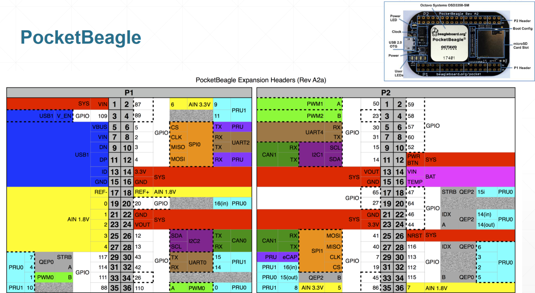
Hardware Set upPocketBeagle
The PocketBeagle should be soldered to headers to allow for jumper wires as shown below. The USB host port should be enabled by soldering the pins shown below.
LevelShifters
Two level shifters (3.3V to 5V) must be used to translate data from the Pocketbeagle to the LED matrix. These should be wired according to the diagram below. (VA to 3.3V rail, VB to 5V rail, GND to GND rail, and OE to VA). Headers also must be soldered on with the long portion of the header facing outwards towards the breadboard. Failure to solder the headers the correct way can result in shorter pins and thus, no connection to the breadboard.
USBBreakout
The USB breakout is used to connect the USB Wifi adapter to the PocketBeagle. To connect it, refer to the wiring diagram by Robert Heeter further down the page.
LEDMatrix
The bulk of the wiring is for the LED matrix. While some board show different pinouts for the data port, all 64 x 32 boards from Adafruit should follow the pinout shown below. With the board in the correct orientation, the data port should be located on the left end of the board. There is an additional port with the same connector which can be easily mistaken for the input but this is the output port.
R1, B1, and G1 control red, blue, and green LEDs for the top half of the matrix. R2, B2, and G2 control their respective color LEDs for the bottom half of the matrix. A, B, C, and D control row outputs while CLK and LAT control timing and column output. OE controls output enabling/disabling. More details on how the LED matrix works can be found here and here. Reviewing these articles can be key in debugging and LED matrix output issues.
To simplify the wiring, the left and right columns of the data port will be separated. The left column pins will all go to the first level shifter and the right will go to the second. For the left column, pins R1 through OE should be wired to B8 through B1 respectively. For the right column pins G1 --> B8, G2 --> B6, B --> B4, D --> B3, and LAT --> B2. The GND pins should be connected to the breadboard GND rail. The overall wiring diagram by Robert Heeter later in the page can be consulted for more info.
To connect the level shifters to the PocketBeagle, jumper wires should be used from the A pins on the levels shifters to their respective PocketBeagle pins. A diagram by Robert Heeter is shown below with the correct pin connections.
The complete wiring can be seen below.
PushButtons
Push buttons should be wired according to the diagram below.
BH1750LightSensor
The BH1750 Light sensor should be wired using the I2C bus located at pins P1_26 and P1_28 for SDA and SCL respectively. VCC should be connected to the 3.3V rail and GND should be connected to the GND rail on the breadboard.
Challenges/FutureWork
The main challenge was getting the LED matrix to work which was never fully resolved. After testing, checking, and validating the wiring for each pin, replacing the LED matrix three times, replacing both level shifter, and replacing the PocketBeagle twice, the same issues still persisted with the LED matrix. Although previous projects were successful with the same wiring scheme and pin selection, my LED matrix consistently experienced issues with size, doubling of the image, and incorrect colors. Future work could be done in replacing the breadboard to see if that is the culprit or replacing each jumper wire with a new one. These could be causing the major issues for me but following the wiring guide above yourself should result in a working matrix! (it has in the past). There were also many challenges regarding the coding logic of the spotify widget and the restrictions from the Spotify API due to Spotify DRM.
Future work can also be done to implement and refine the light sensor. A non-functional LED matrix prohibited me from testing any code regarding the light sensor. As such, the auto-dimming feature can be fleshed out if a working LED matrix is available. For additional features, the color of the visualizer could also be changed to match that of the album art.
All in all, although I am not able to fully show the capability of this device, I am extremely grateful for the chance to work on this project. I dove deep into the unknown worlds of embedded systems and coding and learned so much through the process.
Thank you to Prof. Erik Welsh for guiding me through this process and dedicating his time to help debug with me.


_3u05Tpwasz.png?auto=compress%2Cformat&w=40&h=40&fit=fillmax&bg=fff&dpr=2)
Comments