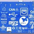
This project contains hardware design for person detection device to help people with low vision or disability. indicator result of detection will be delivered through A2DP Bluetooth transmitter to wireless Headset/Speaker. To be able to perform person sensor detection, main controller/microcontroller will be needed. In this project, an ESP32 board will be used.
SoftwareSoftware that being used to develop the device is KiCAD EDA tools, can be download here. KiCAD is open source software for PCB design, and run on multiple platform/OS. Overall, KiCAD offers solid result on PCB design, easy interface and support multiple board output. KiCAD also give 3D result for PCB Overview before manufactured in PCB production house.
Firmware compiler to run this board is ARDUINO IDE. Main controller of this board is ESP32, Refer to this article on how to enable ESP32 on Arduino IDE.
Hardware Block DiagramHadware block diagram is described in the picture below. This board consist of some component that have it's own functionality. ESP32 will perform data acquisition from other device on the board, store data on memory and process acquired data, and sending information to target.
Block power will produce DC 3.3V/800mA output to supply all of the component on the board. The board need input power above DC 3.3V (3.7V - 5V) to make the board working. This board power conversion is using LM1117.
SDCard block will be used as file storage to store file with huge size. The ESP32 is embedded with 16Mb Flash, which is not suitable to save file with huge size. SDCard and ESP32 will communicate through SPI protocol.
USBtoUart block is external board to help download the firmware to ESP32. Any USB to UART board with RX/TX pins with additional RTS and DTR will work to download the firmware.
IO and Push Button Block will be use as switch to control volume, play and stop the sound. The sound will be transmitted through A2DP to wireless speaker.
Useful sensor will be attached as external board to the main board. The communication to acquire data from useful sensor is using I2C protocol.
Block Power Diagram consist of Battery Charger controller, Chip battery protection, Li-po Battery and boost converter 5V. In this design, Charger controller will use TP4056 chips to control the charging activity. Battery protection is performed by DW01A IC.
The board is designed in 4 Layer PCB with Google Devboard Micro form factor. It is designed to be compatible with Google Devboard I/O pins. The First layer is dedicated for Ground and signal planes, 2nd Layer only for Ground plane, 3rd layer is dedicated for Power propagation, and 4th layer is for Ground and signals layer.
This board is compatible with Useful sensors, connected through QWIIC or JST connector with 1.0 mm space. the board also equipped with automatic downloader switch and manual switch. Due to limited space, USB-to-Uart converter can't be placed on the board.
Power controller board is designed on 2 layers PCB with capability to charge battery with 5V usb input and 5V DC. This board equipped with Battery protection for overcharging or overloading current. To be able to supply main board with 5V, this board also equipped with 5V boost converter.
Demonstration video:
DiscussionThis board is designed to be compatible with Google devboard micro, but the functionality has not been checked since the Google Devboard Micro was having problem with it's firmware. The awarded Devboard micro is bricked and couldn't functioning normally.
Issue submitted but no further feedback here: https://github.com/google-coral/coralmicro/issues/73
Firmware for the board is only performing the basic run for person detection, A2DP and Music playing. Further development might needed to perform more advance tasks.


_4YUDWziWQ8.png?auto=compress%2Cformat&w=48&h=48&fit=fill&bg=ffffff)


_Ujn5WoVOOu.png?auto=compress%2Cformat&w=40&h=40&fit=fillmax&bg=fff&dpr=2)

Comments
Please log in or sign up to comment.