TheIdea:
The idea behind this project was pretty straightforward, I've gotten tired of throwing together little Arduino circuits everytime I want to control a stepper motor in the midst of prototyping a build. I figured there was no reason that I shouldn't just build a little controller, and so I did.
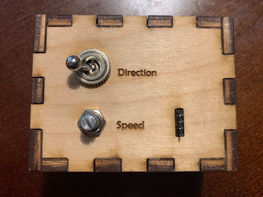
The Product:I'm very pleased with the result. It has an input for 12V, a four pin header for a stepper motor, as well as two control inputs, a potentiometer and toggle switch. I can switch the output direction by flipping the switch, and I can control the speed by turning the potentiometer.
The Build:
This was a pretty straightforward soldering project, with a little frustration because of my lack of understanding of pull-down resistors.
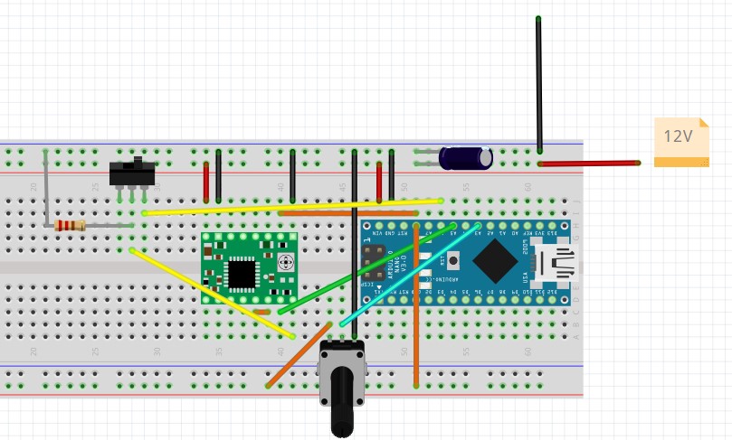
The circuit itself is not overly complicated, and after a quick test, I moved to assembling it on a soldered breadboard. I soon had it functioning with the exception of my switch to flip direction. It would work just fine in one direction and then not at all in the other. After consulting my friend I realized that I was missing a pull-down resistor on the lowside of the switch. Since the a4988 is looking for a high/low input switch to drive direction, my plan was to connect an always high pin on the Arduino to the a4988 with the flip switch in between, however the switch wasn't enough to successully pull down the value at the stepper motor controller. A quick addition of a a pull-down resistor solved this problem nicely.
I then was able to assemble everything into a little laser cut box and tested it with a stepper motor.
Thekeyfeaturesare:
I was satisfied with the project especially considering it was a quick one, with little iteration. And most importantly I can now use it while building other stepper motor projects to easily rotate them in either direction.


_3u05Tpwasz.png?auto=compress%2Cformat&w=40&h=40&fit=fillmax&bg=fff&dpr=2)

Comments
Please log in or sign up to comment.