My initial inspiration for BlindSight came from another device developed by Alex Wulff called HaptoTech. In a presentation to my high school, Alex showcased the device, and I knew I wanted to redesign it and recreate it. Both devices use the general idea of an ultrasonic sensor sending ultrasonic waves to an object and receiving the waves back again. The device works because the code can compute a displacement from the time the wave traveled, neat! It's fairly simple but could be upgraded with a custom PCB, a 3D-printed case, and a strap, making it wearable.
Step One: The BrainsBlindSight uses an Arduino Uno R3, which is very standard in terms of hobby and maker projects. However, the device could be upgraded using a microcontroller developed by Atmel known as the ATtiny85. It is no larger than one's fingertip and can be implemented into a custom PCB. The ATtiny85 comes in the DIP or SOIC 8 variants. The DIP can be easily mounted onto a PCB with a DIP 8 socket. The SOIC 8 is a smaller unit but can prove to be difficult to solder onto a PCB. Nonetheless, if you are satisfied with a larger board, the UNO certainly holds its own for this project.
The Idea and device is useful for those who are visually impaired or completely blind. The idea is to leave the canes at the door and upgrade to a device like this. With these devices mounted, via a strap, over one's body, the user could map their entire environment with vibration amplitudes in their minds. The device could either replace canes entirely or supplement them, while decreasing user fear and increasing user confidence in prolonged movement.
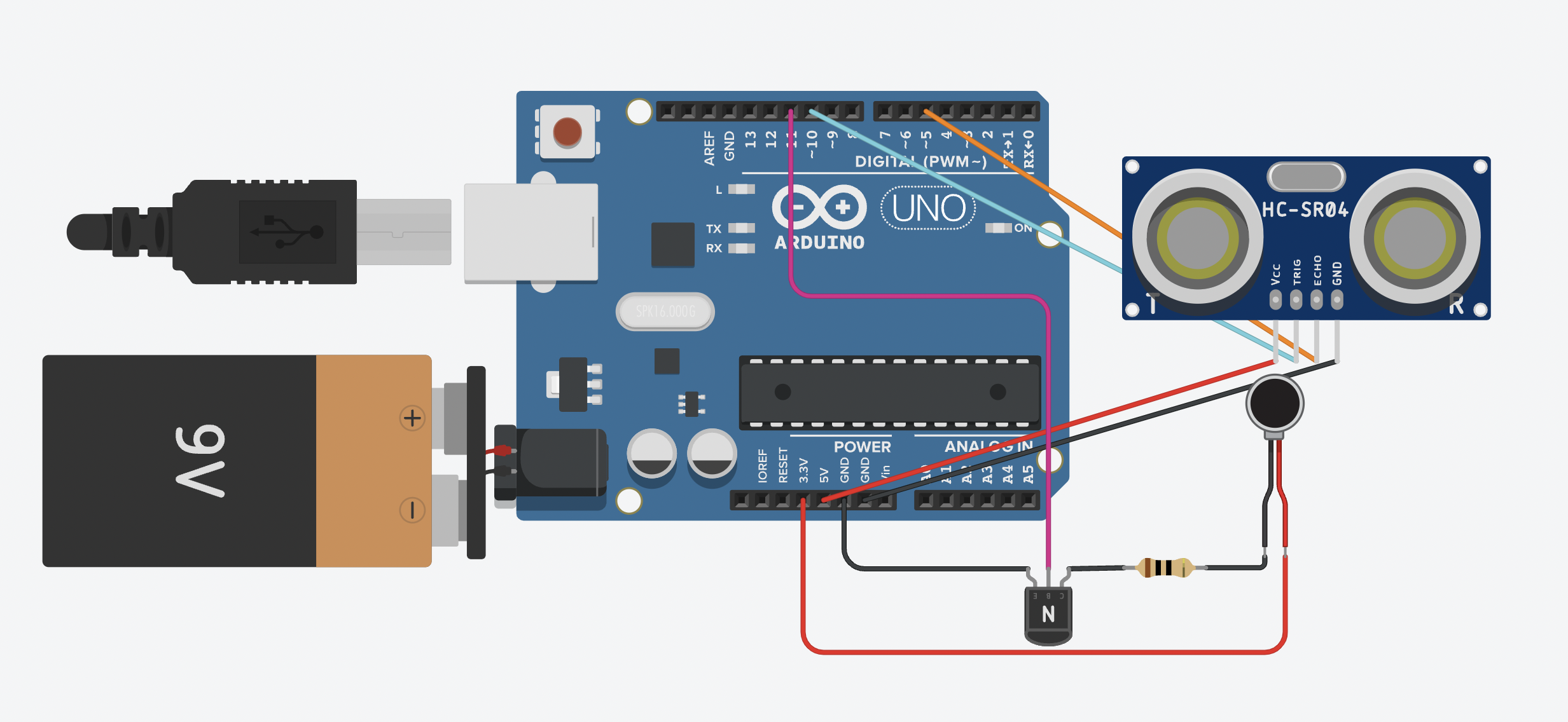
Step Two: The CircuitThe circuit is relatively simple, and the circuit design is consolidated as much as it can be in terms of connections. Given that this was my second project ever, it took some time to create the circuitry needed for varied vibration, that is vibration with varied amplitude. This problem was fixed with the implementation of an NPN transistor. Using an analog voltage pin on the Arduino, the current through the gate would be proportional to the current through the vibration motor. Therefore, as the voltage at the gate increased (a larger analog voltage), the current through the motor would increase, and the motor would vibrate with a larger amplitude. This was the perfect design for this project because I could relate the displacement values to vibration amplitudes (a small displacement = a large vibration amplitude, as to alert someone that there is an object near their sensor).
Step Three: Assembling The DeviceThis device's network of jumper wires isn't the most complicated, but it is important to position them in such away that the sensor is set in place. Once you have connected jumper wires to the leads of the HC-SR04, Vcc, GND, Trig, and Echo, place the sensor on the front of the Uno. Start to wrap the wires around the entire board before plugging the wires into their designated pins, so the sensor is secure. After securing it, you can move onto part two of the circuit: the vibration motor. The emitter region of the transistor must be connected to GND; the base region must be connected to pin eleven, specified in my code; and the collector region must be connected to the other lead of the vibration motor. Then connect the second lead of the motor to 3.3V, as 5V is already used by the HC-SR04. You will also need a 10 ohm resistor in series with the motor. The connections can be made by solder or by wrapping wires and hot-gluing them. Either will work. In order to make the device wearable, you need a portable power source. A nine-volt battery is nicely within the Arduino jack's specified 5-12V range. I would recommend hot-gluing it and any other hanging circuitry to the back of Uno.
Step Four: The SoftwareAbove is some of the code for this device. The code allows the HC-SR04 to talk to the Arduino Uno. Then the UNO interprets this information and makes pre-programmed decisions. As stated before, the code sets the sensor in receiving mode, receives displacement values, and tells the board to deliver current to the vibration motor. This code can definitely be optimized by using code that puts the device into sleep mode when it is too far away from an object to vibrate, or a switch can be added in order to turn it off when it's not being used instead of pulling out the external jack connector cord. These actions would prolong the battery life.
Step Five: Going FurtherAgain, in its current state, the device is hand-held; however, by adding a strap and a 3D-printed case, the device can be put onto someone without any need to touch it or maneuver it. There are also smaller ultrasonic sensors that you can buy to compact this device even more. In all, this device can get very, very small and extremely cheap.
Once I have designed a custom PCB and 3D-printed case, I will be republishing this project with a version two: smaller, more adjustable, and easier to use.
Step Six: DiscoverCheck out my other projects on my dashboard:
- Arduino Uno DIY Drone
- Arduino Smart Traffic Light
- IAADL: an Infrared Activated Automatic Door Lock
- Arduino Functions Library
Check out all of my projects code at my GitHub repository.


_ztBMuBhMHo.jpg?auto=compress%2Cformat&w=48&h=48&fit=fill&bg=ffffff)


Comments
Please log in or sign up to comment.