daniel23
Published © LGPL

Pan and Tilt Head with Very Slow and Fluid Movements

I made this pan and tilt to film village theater from back of the room. Because of the high zoom rate, slow movements are necessary.

AdvancedFull instructions provided5,559
Pan and Tilt Head with Very Slow and Fluid Movements

Things used in this project

Hardware components

Arduino Nano R3
Arduino Nano R3
×1
0.9 degré Nema 16 stepper motor
×1
0.9 degré Nema 14
×1
Jumper Hall Gimbal
×1
TMC2208 Silentstepstick
×2
Prototyping board
×1
Alphanumeric LCD, 16 x 2
×1
Switch Accessory, RJ45 Socket
Any other RJ45 socket can do it
×2
RJ45 cable
×1
SPDT ON-OFF-ON
×1

Software apps and online services

Arduino IDE
Arduino IDE
Pan_and_Tilt_Head.ino and PrintAlign.ino must be copied to a subdirectory "Pan_and_Tilt_Head" before compiling

Hand tools and fabrication machines
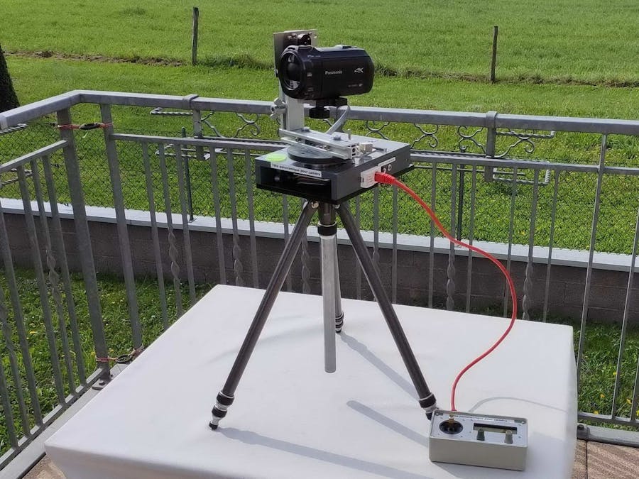
Soldering iron (generic)
Solder Wire, Lead Free
HACKSAW
Drill / Driver, Cordless

Story

Read more

Schematics

Schema Pan_and_Tilt_Head

Pan_and_Tilt_Head_UPDATE

Code

PrintAlign

Arduino
// *******************************************************************
// ************ LCD display 2 digits/numbers  ************************
// Display 16 bit unsigned integers as number and fill mising digits
// with any character if length less than specified by digit
//    ---  maximum value is 2^16, or 65535 ---
// does fill leading missing digits but don't truncate longer number
//        number  : number to display
//        digit   : how much digits
//        fill    : characters to add on the left
// *******************************************************************
void lcdPrintAlign(uint16_t number, byte digit, char fill)
{
  switch (digit)
  {
    //    case 1:         //  1 digits not needed > goes to default
    //    goto Prior;
    //    break;
    case 2:
      goto Secundus;       //  2 digits
      break;
    case 3:
      goto Tertius;      //  3digits
      break;
    case 4:
      goto Quartus;  //  4 digits
      break;
    case 5:
      goto Quintus;   //  5 digits
      break;
    default:          //  not expected
      goto Prior;      //  but print as is
      break;
  }
Quintus:
  if (number < 10000) lcd.print(fill);
Quartus:
  if (number < 1000) lcd.print(char(fill));
Tertius:
  if (number < 100) lcd.print(char(fill));
Secundus:
  if (number < 10) lcd.print(char(fill));
Prior:
  lcd.print(number);
}

Pan_and_Tilt_Head

Arduino
This is the updated file (v2.1). It replaces the first. The added 3-position switch allows now the choice between 3 equations
//         ******************************************
//         *    Pan and Tilt Head for camcorder     *
//         *    Daniel Engel         22/08/2021     *
//         ******************************************
//
//  Please be indulgent about my clumsiness with syntax and coding :
//  I don't speak very well english and I am a newbie in programming.
//
/*
   Stepper motors speed and displacement direction are controlled by a joystick.
   An additional potentiometer adjusts the speed range. A second order equation gives
   better precision for low displacement speeds. As it is very costly in computation
   time, the stepping is initiated in an interrupt routine triggered by timer 2.

   Unfortunately there is hidden snag due to non symetrical joystick voltage excursion.
   Due to the exponential relation the maximum speeds are quite different in each way.
   It might be possible to modify the software to calibrate the joystick voltage
   values at startup and remap them to symmetrical values.

   The stepper motors I have used are 0.9 per step. They are driven in 1/16 step.
   Since the camcorder should shoot at high zoom so additionnal reduction was needed
   for smooth movement. The drive is done by timing pulleys and belts with a reduction
   ratio of 15 to 60 teeth for the tilt and 15 to 160 teeth for the panning.
   The 160 tooth timing pulley was not readily available. A smooth pulley was machined
   in a pvc piece on a lathe. The drive is done by friction with the timing belt.

   Many thanks to Mike McCauley for his AccelStepper library for Arduino
      https://github.com/waspinator/AccelStepper/

   and Frank de Fmap for "Arduino-LiquidCrystal-I2C-library"
      https://github.com/fdebrabander/Arduino-LiquidCrystal-I2C-library

   =================================================================================
   Hardware that I've used
   =================================================================================

   The mechanism is made so that the center of gravity with mounted camcorder is very
   close to the axes of rotation. So everything can turn with minimal resistance.
   The ball bearing assembly for the panning was recovered from a old VCR head.
   For the tilt, two ball bearings were mounted in an aluminium profile.
   ---------------------------------------------------------------------------------
   >>>  Arduino NANO (or Pro Mini with modification to bring out Vref pin)
   >>>  CNC Shield for Stepper Motor Driver
   >>>  TMC2208 V1.2 Stepper Driver Module (the quietest driver I have tried)
         drv8825 will also work but they are quite loud...
   >>>  16x2 Character LCD Display with I2C interface
   >>>  50 KOhm linear potentiometer for speed range
   >>>  50 KOhm linear potentiometer for backlight brightness
        (with 100nF capacitors between Arduino's analog inputs and ground)
   >>>  5V regulator (e.g. 7805 or 78L05)
   >>>  12V-3A Power Adapter

   >>>  NEW: a 3 position SPDT switch Centre Off (ON-OFF-ON)

   -------------------------------------------------------
   >>>  Vertical Stepper motor (tilt): STH-39C8011-03  <<<
   -------------------------------------------------------
      0.9 degr Nema 16 (39*39mm, height: 19.5mm)
      Resistance: 5.3 ohms
      Torque: 0.13 N.m @ 0.98A (in the real wolrd only abour 2/3 of that...)
      Weight: 98g
   Since the motor gets quite hot at this current and the torque is more than enough
   for my camcorder (weight is about 420g), the current is set to the double of minimum
   needed for sufficient torque, say 0.4A ....???

   -------------------------------------------------------
   >>>  Horizontal Stepper motor (pan): 14H33HM-0404A2  <<<
   -------------------------------------------------------
      0.9 degr Nema 14 (35*35mm, height: 27.5mm)
      Resistance per Phase ~6.5 ohms
      Torque: 0.15 N.m @ 0.82A (same remark as above about the real torque !)
      Weight: 132g
   Current is set to double of min needed for sufficient torque, (0.4A)

   -------------------------------------------------------
   >>>  Jumper Hall Gimbal Product Code: JMP-P10107  <<<
   -------------------------------------------------------
 	  Supply Voltage: DC 3.0 ~ 3.5V   (3.3V is fine)
      Pay attention to the connection. On mine the wiring is a bit strange:
      the  red wire is GND, the black wire is + 3.3V and the yellow wire is Vout.

         Joystick position      analogRead / (measured voltage (Aref = 3.3V)
                                Horizontal         Vertical
                 min	          200 / (0.61V)     197 / (0.56V)
                center	        577 / (1.63V)     570 / (1.61V)
                 max 	          950 / (2.65V)     905 / (2.55V)

    The voltage excursion is not completely symmetrical for movements in the min and max directions.

  New in "Pan&Tilt v2.1":
  
    - Replaced some "#define" with "const".
    - Serial.print are commented out in the "loop"
    - There was error in the formula: value was first divided and then squared instead of the reverse
      The formula is now corrected and the factors are updated (the curve is the same than before).
    - In some situations the speed increase is growing too quickly at the end of the joystick stroke.
      So I added a switch according to the state of which the equation is changed dynamically in the
      procedure "CalculateSpeed".
      Note: the position of the switch is displayed on the LCD screen (Lin. Fa. Or Sl.)
            but is only refreshed when a movement is requested by the joystick.
*/

#include <math.h>
#include <AccelStepper.h>
#include <Wire.h>
#include <LiquidCrystal_I2C.h>
LiquidCrystal_I2C lcd(0x27, 16, 2);     //  address 0x27 - / 2 line - 16 chars LCD display
//LiquidCrystal_I2C lcd(0x3f, 16, 2);   //  address 0x3f

#define VersionMsg "Pan&Tilt v2.1"     //

const byte joyHorizontal = A0;    // Joystick X pin
const byte joyVertical = A1;      // Joystick Y pin
const byte speedPot = A3;         // Master speed potentiometer
const byte lightSensor = A2;      // Light Sensor (in fact it's another potentiometer)
const byte step_pulse_X = 3;      // Horizontal  Axis
const byte step_pulse_Z = 2;      // Vertical  Axis
const byte direction_X = 5;       // Horizontal  Axis
const byte direction_Z = 4;       // Vertical  Axis
const byte pwmLCD = 9 ;           // PWM pin for LCD backlight (see I2C interface modification diagram)

/*  3 position switch added to select the equation in "CalculateSpeed"

         selectLinear      selectLaw     Response to joystick movement
            closed          Open           linear
             Open           Open           exponential - slightly Faster growth in the beginning
             Open          closed          exponential - Slow growth at the beginning
*/
const byte selectLaw = 7;         // Added for selecting equation in CalculateSpeed()
const byte selectLinear = 6;

// Define the stepper motors and the used pins  (Type of driver, STEP_PIN, DIR_PIN)
AccelStepper stepperHorizontal(1, step_pulse_X, direction_X);   // HORIZONTAL (X Axis on the stepper shield)
AccelStepper stepperVertical(1, step_pulse_Z, direction_Z);     // VERTICAL (Z Axis on the stepper shield))

int joyHorizontalPos = 0;
int joyVerticalPos = 0;
int PotValue = 0;                 // "Speed" potentiometer
int restHorizontal = 0;           // Joystick rest position
int restVertical = 0;
int deadZoneHorizontal = 40;      // Dead zone (without movement)
int deadZoneVertical = 100;       // On my joystick, less than 80 lead to errors when moving down
float scaleHorizontal = 8;        // Divider to map to full speed (scale is in the denominator)
float scaleVertical = 32;         // Divider to map to full speed (smaller value => greater speed)
//                                   vertical (tilt) should move more slowly than horizontal (pan)
float hSpeedValue = 0;
float vSpeedValue = 0;

// byte portD;                    // selection pins for the equation used are 6 and 7
const byte mask =  B00000011;     // used after bit shift (portD, bits 6 and 7) to invert the logic

byte customCharUp[8] = {          // up arrow
  B00000,
  B00000,
  B00100,
  B01110,
  B11011,
  B10001,
  B00000,
  B00000
};
byte customCharDown[8] = {        // down arrow
  B00000,
  B00000,
  B00000,
  B00000,
  B10001,
  B11011,
  B01110,
  B00100
};


void setup() {
  
  /*   The direction of the motion can be inverted with following instruction:
   *   stepperX.setPinsInverted( direction, step, enable);     // as boolean (true / false)
   *   another way is simply to reverse the motor connectors
  */
  // Note that the direction of rotation is reversed with TMC2208 drivers instead of DRV8825
  stepperHorizontal.setPinsInverted( true, false, false);     // Pan direction is inverted
  //stepperHorizontal.setPinsInverted( false, false, false);     // Pan direction is inverted
  stepperVertical.setPinsInverted( true, false, false);
  //stepperVertical.setPinsInverted( false, false, false);
  // Set initial speed values for the steppers
  stepperHorizontal.setMaxSpeed(4000);
  stepperHorizontal.setAcceleration(200.0);
  stepperHorizontal.setSpeed(200);
  stepperVertical.setMaxSpeed(4000);
  stepperVertical.setAcceleration(200.0);
  stepperVertical.setSpeed(200);

  pinMode(selectLaw, INPUT_PULLUP);
  pinMode(selectLinear, INPUT_PULLUP);

  Serial.begin (115200);
  Serial.println ("*** Test AccelStepper with ISR on timer2 (~125s ***)");

  lcd.begin();                          // initialize the LCD
  lcd.noBacklight();                    // lcd.backlight(); shall be "OFF" so that the PWM can works
  lcd.createChar(6, customCharUp);      // down arrow at CGRAM(7)
  lcd.createChar(7, customCharDown);    // down arrow at CGRAM(7)
  lcd.home();
  lcd.clear();
  lcd.setCursor(0, 0);
  lcd.print(VersionMsg);
  Serial.println (VersionMsg);
  delay (2000);

  analogReference(EXTERNAL);  // the 3V3 is connected to Aref with a resistor of 1K (recommended value is 5K)
  delay (250);
  PotValue = analogRead(speedPot);      // Dummy read (first read may be false after analogReference change)
  delay (250);
  PotValue = analogRead(speedPot);            //  Speed multiplier (not used this time - Value is updated in loop() )
  restHorizontal = analogRead(joyHorizontal); // Joystick X - Pan movement
  restVertical = analogRead(joyVertical);     // Joystick Y - Tilt movement

  TCCR2B = 0x00;                        // Disable Timer2 while setting up
  TIFR2  = 0x00;                        // Timer2 INT Flag Reg: Clear Timer Overflow Flag
  TIMSK2 = 0x01;                        // Timer2 INT Reg: Timer2 Overflow Interrupt Enable
  TCCR2A = 0x00;                        // Timer2 Control Reg A: Wave Gen Mode normal

  /*   This seems to be best compromise for interruptions between Fmax and regularity of rotation
       => shortening this time is done to the detriment of the time available for the calculation
  */
  TCCR2B = 0x02;                        // Timer2 Prescaler set to 8 (~255s)
  TCNT2  = 12;                          // -> do not forget to add it in the ISR !!!
  /* Setting low bits of TCCR2B  //  TCCR2B = (TCCR2B & 0b11111000) | <setting>;
        Setting   Divisor   Frequency
          0x01      1       31372.55
          0x02      8       3921.16
          0x03     32       980.39
          0x04     64       490.20   <--DEFAULT PWM
          0x05     128      245.10
          0x06     256      122.55
          0x07    1024      30.64
  */

  //      Pins 6 and 7 are used to select the equation to be used
  for (byte i = 6; i <= 7; i++) {   // never modify pins 0 and 1 (RX andTX)
    //    Serial.print (i);
    pinMode (i, INPUT_PULLUP);
  }
}

void loop() {
  lcd.setCursor(0, 0);
  //          1234567890123456    // (This line is usefull for positionning text in the LCD 16 chars line)
  lcd.print ("Horiz.Vert.Speed");   // Pot.
  PrintMove();                    //  Displays arrows to visualize motion direction

  PotValue = analogRead(speedPot);                //  Speed multiplier
  PotValue = map(PotValue, 0, 1023, 10, 255 );    // map(value, fromLow, fromHigh, toLow, toHigh)

  // => PWM for LCD backlight ~100mA with "analogWrite(160)
  // Change the "map" value to meet your requirements
  // for modern LCD backlights 20 to 30 mA shall be enough
  // To limit current the jumper on I2C interface can be replaced by a resistor (100 to 470 Ohm)
  analogWrite(pwmLCD, map(analogRead(lightSensor), 0, 1023, 10, 120 ));

  lcd.setCursor(13, 1);
  lcdPrintAlign(PotValue, 3,  ' ');

  //  *******************************************************************
  //      Joystick X - Pan movement (Horizontal)
  //  *******************************************************************
  joyHorizontalPos = analogRead(joyHorizontal);   // Joystick X - Pan movement

  // if Joystick is moved left, move Horizontal stepper - pan to left
  if (joyHorizontalPos > (restHorizontal  + deadZoneHorizontal)) {
    hSpeedValue = (joyHorizontalPos - (restHorizontal + deadZoneHorizontal));
    hSpeedValue = CalculateSpeed ((float)hSpeedValue, (int)PotValue, (float)scaleHorizontal );
  }
  // if Joystick is moved right, move Horizontal stepper - pan to right
  else if (joyHorizontalPos < (restHorizontal - deadZoneHorizontal)) {
    hSpeedValue = ((restHorizontal - deadZoneHorizontal) - joyHorizontalPos);
    hSpeedValue = -CalculateSpeed ((float)hSpeedValue, (int)PotValue, (float)scaleHorizontal );
  }
  // if Joystick stays in middle, no movement
  else {
    hSpeedValue = 0;
  }
  stepperHorizontal.setSpeed(hSpeedValue);
  //  Serial.print("h_Speed: ");
  //  Serial.println(hSpeedValue);

  //  *******************************************************************
  //      Joystick Y - Tilt movement (Vertical)
  //  *******************************************************************
  joyVerticalPos = analogRead(joyVertical);       // Joystick Y - Tilt movement
  /*
    if (joyHorizontalPos > (restHorizontal  + deadZoneHorizontal)) {
      hSpeedValue = (joyHorizontalPos - (restHorizontal + deadZoneHorizontal));
      hSpeedValue = CalculateSpeed ((float)hSpeedValue, (int)PotValue, (float)scaleHorizontal );
  */
  if (joyVerticalPos > (restVertical + deadZoneVertical)) {
    vSpeedValue = joyVerticalPos - (restVertical + deadZoneVertical);
    vSpeedValue = CalculateSpeed ((float)vSpeedValue, (int)PotValue, (float)scaleVertical );
  }
  /*
    else if (joyHorizontalPos < (restHorizontal - deadZoneHorizontal)) {
    hSpeedValue = ((restHorizontal - deadZoneHorizontal) - joyHorizontalPos);
    hSpeedValue = -CalculateSpeed ((float)hSpeedValue, (int)PotValue, (float)scaleHorizontal );
  */
  else if (joyVerticalPos < (restVertical  - deadZoneVertical)) {
    vSpeedValue = ((restVertical - deadZoneVertical) - joyVerticalPos);
    vSpeedValue = -CalculateSpeed ((float)vSpeedValue, (int)PotValue, (float)scaleVertical );
  }
  else {
    vSpeedValue = 0;
  }
  stepperVertical.setSpeed(vSpeedValue);
}

//  *************************************************************************
//  Calculate speed (The last tested quadratic equation seems most pleasant)
//       Note: when calling the "int" are converted into "float"
//  *************************************************************************

float CalculateSpeed (float value, float factor , float scale) {
  float tempValue;
  byte portD;

  portD = PIND;        // gets bits 6 and 7 in LSB
  portD = portD >> 6 ;           // gets bits 6 and 7 in LSB
  portD = portD ^ mask;         // bit inversion

  /*   The switch has 3 positions: "1 - 0 - 2" for " UP - MIDDLE - DOWN. So I choosed:
       linear is DOWN, MIDDLE is slow exponential growing and UP is fast exponential growing
       Note: The position of the switch is only refreshed on the LCD screen AFTER a movement !
  */

  lcd.setCursor(9, 1);
  switch (portD) {        // remember: bit 7 and 6 were shifted right to bit 1 and 0

    case 0:               // Exponential - FAST growing at the begin (tumbler switch is MIDDLE)
      //      Serial.print ("Case 0 - Slow :  ");
      //      Serial.print (value);
      //      Serial.print (" : ");
      lcd.print (" Fa.");                    // display "Fa." in front of "potvalue"
      tempValue = (((((sq(value)) / 3200) + (value * 0.198)) * factor) / scale);   // ((x^2)/3200)+ 0.198x
      //     tempValue = (((((sq(value)) / 1600) + (value * 0.1)) * factor) / scale);   // ((x^2)/1600)+ 0.1x
      break;

    case 1:               // Exponential - SLOW growing at the begin (tumbler switch is DOWN)
      //      Serial.print  ("Case 1 - Fast :  ");
      //      Serial.print (value);
      //      Serial.print (" : ");
      lcd.print (" Sl.");                    // display "Sl." in front of "potvalue"
      /*
         tempValue = (((sq(value / 40) + (value * 0.1)) * factor) / scale);   // ((x/40)^2)+ 0.1x

         There was an error in previous formula: the value is first divided and then squared.
         Below is the corrected with the updated factors.
         The results are the same but the reasoning was wrong ...
      */
      tempValue = (((((sq(value)) / 1600) + (value * 0.1)) * factor) / scale);   // ((x^2)/1600)+ 0.1x
      break;

    case 2:               // LINEAR law (tumbler switch is UP)
      //      Serial.print  ("Case 2 - Lin :  ");
      //      Serial.print (value);
      //      Serial.print (" : ");
      lcd.print ("Lin.");                    // display "Lin." in front of "potvalue"
      tempValue = (((value * 0.296) * factor) / scale);   // 0.296x
      break;

    case 3:
      //      Serial.println  ("Case 3");  // not used with a single 3 positions switch
      break;

    default:
      //      Serial.println ("There is an unforseen case !");
      break;
  }
  //-------------------------------------------------------------------------
  //  Serial.println (tempValue);
  return tempValue;
}


//  *************************************************************************
//  Display motion direction
//  *************************************************************************
void PrintMove() {

  // Visualize Horizontal motion
  lcd.setCursor(1, 1);
  if (hSpeedValue < 0)  {
    lcd.print (">>>");
  }
  else if (hSpeedValue > 0)  {
    lcd.print ("<<<");
  }
  else {
    lcd.print ("   ");
  }

  // Visualize Vertical motion
  lcd.setCursor(5, 1);
  if (vSpeedValue < 0)  {
    for (byte i = 0; i <= 2; i++) {
      lcd.write(6);;      // customChar "up arrow"
    }
  }
  else if (vSpeedValue > 0)  {
    for (byte i = 0; i <= 2; i++) {
      lcd.write(7);;      // customChar "down arrow" could be replaced with: lcd.print ("vvv");
    }
  }
  else {
    lcd.print ("   ");
  }
}

//  *************************************************************************
//  This is now the heart and secret for smooth and fast running
//  stepper motors with the AccelStepper library
//  *************************************************************************
ISR(TIMER2_OVF_vect) {
  TCNT2 = 12;
  stepperHorizontal.runSpeed();
  stepperVertical.runSpeed();
}

Credits

daniel23

daniel23

8 projects • 10 followers

Comments