This project has been developed for educational purposes and can be used in the field of robot development.
Robotics is becoming accessible and easy to control. Nevertheless, it is necessary to pay particular attention to some technical aspects. Especially the handling of servo-motors.
The project uses components that are easily found on the market. Once the components assembled they will be coordinated by an Arduino program. This program will be the focus of the project.
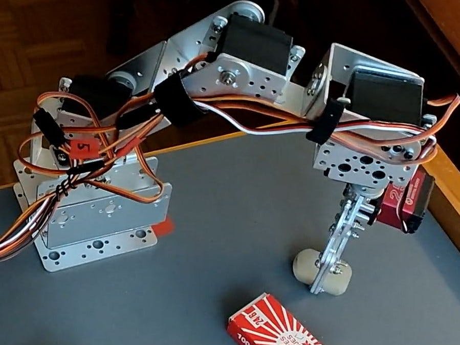
The robot is an articulated arm that moves on three axes (moved by 6 servos). The arm will be programmed to record its positions. Once recorded, a sequence of positions can be automatically replayed and the arm animated.
The positions will remain stored when the power is cut.
All is controlled by a smartphone using a Bluetooth app.
This project focuses quality of assembly and programming (at least I tried 😉 ). It will develop points of vigilance to ensure optimal operation.
Library calls & DefinitionsThe program uses three files: a main program and two functions files. The use of functions avoids code repetition and makes reading easier.
Declaration of the LCD display.
If the display is not used, you can leave the declaration (possibly add the library to Arduino even if not used later). The variable " lcdpres " will be initialized to 0.
Declaration of the Eeprom memory.
The address on the I2C bus is 0x50. The table " eprdata " is used as a buffer for exchanges with the memory. It contains 6 bytes corresponding to the 6 servos and to a given position of the arm. The stroke of a servo going from 0 to 180 is stored in a byte. We will thus use 6 bytes per arm position. These 6 values will then be called sequences and will be read or write to the memory.
We use two pointers or sequence numbers. A pointer for the number of the current sequence and a pointer for the number of the last sequence recorded in the Eeprom memory.
The "eptactmax" array contains the values of these two pointers.
Bluetooth declaration.
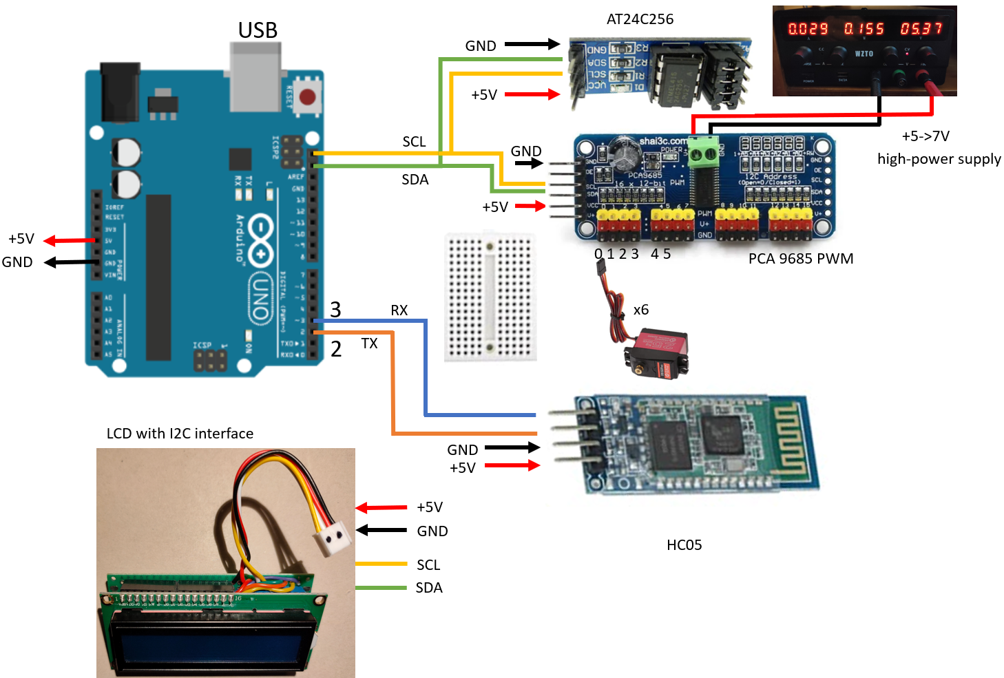
The module is wired on pin 2 and 3 of the Arduino board. The variable " bluerec " contains the received information (alphabet character). In this project the Remote application will send only one character per action.
Declarations for the servo controller. This part deserves the most attention.
The address on the I2C bus is 0x40. The program uses the rotation angle (0 to 180) for positioning the servos. The rotation is carried out by the PWM controller which uses pulses whose width (500 to 2500µs) varies according to the angle. The communication with the controller is done by the " servowrite " function (will be developed later) which will carry out beforehand an angle-pulse conversion. The MAX and MIN variables are used for this conversion. Depending on the servo model these values can change. In our case the MG996 servos have a rotation angle covering 180°. The replacement servos DS3225 have an angle of 270°. We will keep the 180° rotation because a 270° rotation is not mechanically possible for this arm.
In the assembly some servos cannot rotate over the whole 180° range. They will be mechanically blocked by the supports and will start to heat up. It is therefore necessary to protect them by limiting their stroke. The "tabanglim" table contains the limit values for rotation of each servo (min and max).
The "homepos" table contains the position of the arm at power-up. It is recommended to bring the arm back to this position before switching off. The arm will then already be in position when you restart the program. If the arm is in another position, an abrupt movement will take place on power on. It is advisable to be careful when switching on.
All these values are to be updated if you realize this project!
Structure of the information stored at the beginning of the Eeprom memory: AMHHHHHH1111222222223333334444
Each character represents a byte of memory. "A" is the value of the current sequence pointer (1 to n). "M" is the value of the last recorded sequence (4 in this case). "111111..444444" are the servo positions for the sequence 1...4. "HHHHHH" is sequence 0 and corresponds to the initial position of the arm.
On power-up "HHHHHH" is regraved into the eeprom from the "homepos" table; "A" and "M" are read from the eeprom and stored in the "expactmax" table.
Setup - peripherals initializationThe following functions are used: "lcdw", "readeeprom(x, y)", "writeeeprom(x, y)" and "servomove(a, b)".
"x" represents the address of the starting byte to be read, "y" represents the number of bytes to be read or written, "a" the number of the sequence on the Eeprom, "b" will be explained later.
For easy programming HHHHHH is read back into the eeprom from the "homepos" array; A and M are read from the eeprom and stored in the "expactmax" array. The arm is positioned in its starting position. Here "A" represents the sequence 0 and points toHHHHHH.
Main - several nested loopsThe main loop concerns the reception of a character from the Bluetooth. Depending on the character received, an action is performed.
From " A " to " L " we move manually a servo with a left or right rotation (function " servowrite "). We jump now to the "while" loop. The servo rotates until the character " S " is received. "S" is sent when the button on the smartphone is released. Her we control also the servo's course to prevent it from bumping into the support.
Receiving the characters "M" to "9" leads to special operations.
· "M" and "N" act on the sequence pointer by increments or decrements of 1.
· "Y " displays the angle of the 6 servos and the value of the two sequence pointers.
· "Z" moves the arm from its current position to the initial position.
· "1 " to " 4 " move the arm from its current position to the position corresponding to sequences 1 to 4.
· "8 " moves the arm from its current position to the position corresponding to the selected sequence (sequence selected by " M " and " N ").
· "7 " displays the first 100 bytes of the Eeprom on the serial port.
· "9 " records the current position of the arm (sequence selected by " M "and " N ").
· "6 " starts a succession of movements defined in the " prog " table (" scenario " function) and corresponds to playing a scenario.
// Other variables =====================
int prog[2][10] = {{2, 5, 6, 3, 7, 8, 4, 9, 11, 0}, {0, 1, 0, 0, 1, 0, 0, 1, 0, 0}}; // video scenario
In the above example the arm will move successively to the positions indicated by the sequences 2, 5, 6, 3 etc.
Important note :
Before the execution of the sequence the arm will perform an upward movement. This movement can be inhibited. This is the case in the example for sequences 5, 7 and 9 (for this purpose the second part of the "prog" table is used). Sequences 5, 7 and 9 correspond to the closing of the gripper to grasp an object. The arm must remain in place for these operations.
Moving the arm to a destination position(For a better readability download the.ino program)
The principle of the move is based on the simultaneous (seemingly) rotation of the servos. It would have been simpler to rotate one servo after an other toits destination position. The visual effect is then not smooth and the movement jerky.
The program is therefore a bit more complex. We operate in batches of servos. Each servo is rotated step by step in turn.
1. The servos are numbered from 0 (base) to 5 (clamp). The rotation is done in the following order:
2. The batch consisting of servos 1, 2 is moved upwards independently of the sequence.
3. The batch composed of servos 0, 3, 4 is moved according to the sequence values.
4. The batch composed of servos 1, 2 is moved according to the sequence values.
5. The batch 5 (the clamp) is moved according to the sequence values.
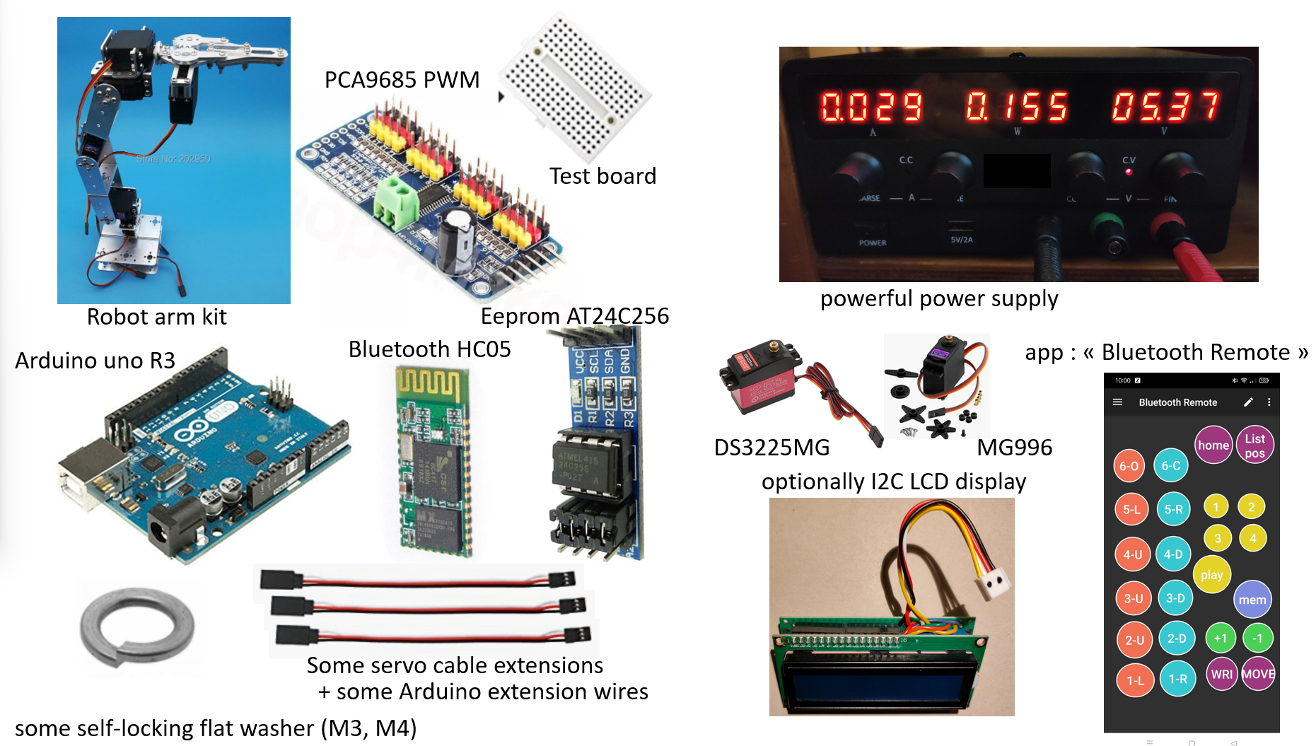
Android applicationTo control the arm we use a smartphone or a tablet with the "Bluetooth Remote" app. This free app is easy to configure. The app is based on the creation of programmable buttons. For each button we define a sequence of characters to send via Bluetooth. The Arduino equipped with the HC05 module will receive the information and transform them into actions.
The modifications of the panel are done by entering the update mode (1). Each button can be modified in size, position and orientation (2). By clicking on a button we can update the button data (3) or add a new button (4).
Note: The two rows of buttons on the left use the value "S" in the "On Press Up" area. When the button is released "S" is sent to the Arduino (used in CASE "A" to "L" of the program).
ConclusionAmong the files to download is a version using the control of servos by the Arduino board directly (using ports 4 to 9) without the PCA9685 controller. The assembly is more complex because the wiring is important.
This project was developed for educational purposes and can be used as a basis in robots developping. You can now give free rein to your imagination for the modelisation of your robots. Enjoy it !


_ztBMuBhMHo.jpg?auto=compress%2Cformat&w=48&h=48&fit=fill&bg=ffffff)


Comments
Please log in or sign up to comment.