When you walk into a dark room, it’s nice to have an LED light strip automatically turn on. But wouldn’t it be cooler if it were controlled by a smartphone – that with a tap of a finger the light could change color? What if, with just a few sliders on your phone’s app, you could create virtually any color with varying intensity, for example sunrise colors in the morning and sunset colors in the evening? This Smart Ambient Lighting system would be able to detect where you are: if you’re simply walking by in the periphery of the room or if a baby is crawling in the hallway in another part of the house. Below is a schematic overview of the Smart Ambient Lighting project.
Possible application of Smart Ambient Lighting.
The Remote Control module (ESP8266 with motion sensor) communicates via Wi-Fi with the Light Control module (Arduino Yun with motion sensor, buzzer, and LED Strip). This system not only provides soothing ambient lighting in a family room, but can effectively be used for monitoring a baby or pet moving in the hallway. The possibilities are limitless! All these sensors can be easily accessed on the Cayenne dashboard from a smartphone or laptop. As an additional bonus, I added a Raspberry Pi which communicates with the Yun and takes pictures when motion is detected in the Family Room (not part of this project). Using Cayenne, I set up a schedule for the Ambient Lighting to go on at sunset. Cayenne also provides options for triggers and alerts to further enhance your lighting system.
ESP8266 Remote Control Module and Cayenne Dashboard on PC
Smart Ambient Lighting and Cayenne Dashboard on Smartphone
Instructions for the Yún Light Control Module:
The first step is to setup the LED strip with the Arduino. This link provides the tutorial for connecting the RBG LED strip to a microcontroller: https://learn.adafruit.com/rgb-led-strips?view=all. The section on “Wiring” shows how to solder four wires to the copper pads on one of the ends of the LED strip. I found that on one end of the strip the manufacturers had already done this, so you may be able to skip this step. However, since you might choose to have your microcontroller several feet away from the LED strip, you will need to solder the three wires from the Micro Connectors cable to the RGB ends from the strip. You will also need to solder the Shaxon wire to the +12V wire from the strip (this needs to be thick because it carries three times as much current as RGB wires, e.g. 14AWG). Connect up the wires as shown in the diagram.
RGB LED Strip connected to Arduino.
The grounds from the three transistors must be connected to the Arduino Yún in addition to the ground of your 12V DC power adapter (the batteries indicate the 12V power supply – don’t actually use batteries). The thick wire you just soldered from the +12V of the LED strip should be soldered on the other end to the positive side of your 12V DC power adapter. The diagram shows the digital pins used: pin 3 for RED, pin 5 for GREEN, and pin 9 for BLUE. Use any GPIO pins that you want, just be sure to alter the code accordingly. If you choose to test using the code provided by Adafruit in the link above, power up your microcontroller, plug in the 12V adapter, and upload your program (using the Arduino IDE). It should work like in the video at the top of Adafruit’s tutorial. Now you’ve completed the first part!
Now, to make it motion controlled – you will need the PIR to detect motion. It is very easy to connect, just three wires: GND, VCC, and OUT (sometimes labeled on the back of the sensor itself). This link contains the tutorial on how to use this sensor: https://learn.adafruit.com/pir-passive-infrared-proximity-motion-sensor?view=all. It’s a good read, but also long, so you can simply wire it up according to this diagram.
PIR with Arduino
Once again, you can use any I/O pin, just make sure to change the code to match your wiring. The link provides an example code which you can use to test your work, which I have modified to make it simpler. Upload this program, and open the serial monitor. Wave your hand near the sensor, and “Motion detected!” should appear on your screen.
PIR Sample Code
Next are the photocells – we only want the light to turn on when it is dark. I used four photocells in parallel with a 10k resistor connected in the same format as https://learn.adafruit.com/photocells?view=all, under “Using a Photocell”.
Photocells with Arduino
Once again, utilize their example code to test your work. Just upload the program as it is (and adjust your input pin to match your wiring) and open the Serial window to observe if your readings match your intuition (shine a light on the cells to see if values approach 1023, and cover them to watch the values drop toward 0).
To create some audio feedback, which is especially useful in alerts, connect a piezo speaker to the Arduino. The positive side goes to a digital output pin, and the negative side to ground.
Speaker with Arduino
With all the pieces together, the project looks like this (scroll through images):
1 / 6 • Front View of Light Control Module
The Light Control Module can also be made by replacing the Yún with another ESP8266 board, with alterations to the code. Since this part of the project uses only 1 analog pin and 5 digital pins, it is possible to use Sparkfun’s board as a substitute.
Instructions for the ESP8266 Remote Control Module:
The Sparkfun ESP8266 board will contain the following sensors:
· IR Receiver / Transmitter
· Some photoresistors
· RGB LED
The IR transmitter, which looks like an LED, sends out pulses at a frequency of 38 kHz. The positive (longer) leg is connected to the digital pin via a 2k Ohm resistor, and the negative side is hooked up to ground. The IR receiver has 3 pins: the left pin (when facing it) is connected to a digital pin via a 220 Ohm resistor. The middle pin is hooked up to GND, and the right pin receives +5V. Here, you can also use an IR distance sensor to adjust the intensity of the light based on the measured distance.
IR Transmitter / Receiver with ESP8266
The next step is to add the RGB LED, so that when motion is detected we have a visual feedback. These LEDs are really cool – with only one digital pin you can control the red, green, and blue values, so you can create virtually any color! Since the ESP8266 has Wi-Fi capability, I was able to use Weather Underground’s API to get the outside temperature and color code it. If you want, you can use the LED’s color to update you if your favorite team won, or if you have unread emails in your inbox. The hardware is simple: one pin to ground, another to 5V, and a third to a digital pin. The LED has a tiny chip inside it, and it decodes a signal sent from the microcontroller to determine what color to display. This complex part is wrapped up in the Adafruit NeoPixel library.
RGB LED added to ESP8266
The final part is to add some local photoresistors to detect lighting wherever you place your ESP board. We are going to use the ADC pin, which is also known as A0, to receive an analog value of the intensity of light present. I decided to use two photocells in series with a 10k Ohm resistor, but you may choose to hook up the cells in parallel, or use a different number of cells. Below is a schematic of the final ESP8266 circuit, with the added photocells.
Photocells added to ESP8266
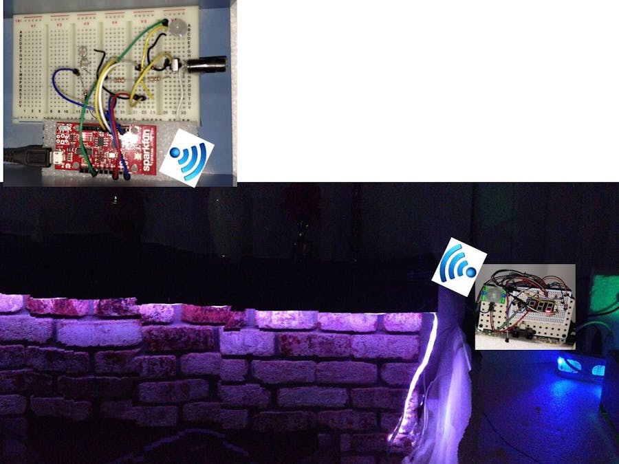
With all the pieces together, the Remote Control Module looks like this:
Picture of Remote Control Module
Here are some screenshots of the Cayenne Dashboard:
This is the Light Control Module which uses a PIR sensor, a buzzer, and some photocells to drive the LED strip. The 32U4 chip receives a code from the AR9331 processor via the Bridge.
/* This is the Arduino code for the Smart Ambient Lighting Project * Upload this code to an Arduino Yun. * * The microcontroller is connected to an RGB LED Strip, a PIR * Sensor, some photocells, and a buzzer. When motion is detected * and the room is dimly lit, the LED strip will turn on until * motion is no longer detected. Then, the buzzer will sound and * the lights will turn off. If it receives a signal from the * Linux side of the Arduino through Bridge, the lights will turn * on according to the temperature outside. This program is also * compatible with Cayenne. * * Created by Daniel Martin */#define RED 3 // Pin connected to gate of Red Transistor (must be PWM)#define GREEN 5 // Pin connected to gate of Green Transistor (must be PWM)#define BLUE 9 // Pin connected to gate of Blue Transistor (must be PWM)// Virtual Pins for Cayenne sliders to control the lights#define REDVP 3#define GREENVP 4#define BLUEVP 5intirDistance=8;intirDistPlus=5;intpiezoPin=4;// pin for buzzer// threshold for light intensity// increase the value if you want the lights to turn on even if the room is lit// decrease the value if you want the lights to turn on only if it's very darkintthreshold=700;charDvalue[2];// variable to take in temp-range value from ESP8266//When light is on, wait 60s //After time limit, wait 30s and check if the number of movements is greater than PIRNUMintpirNum=0;// initialize pirNum to 0unsignedlongextraTimeLim=30000;unsignedlongtimeLim=60000;intPIRNUM=0;intnextmode=0;#define CAYENNE_PRINT Serial // Comment this out to disable prints and save space#include<stdio.h>#include<Console.h>#include<CayenneYun.h>// This token is found in the configuration of your Yn in cayenne.mydevices.comchartoken[]="**********";unsignedlongtimer;unsignedlongextraTime;intphotoPin=0;// Analog pin connected to photocellsintphotoReading=0;intpirPin=7;// Digital pin connected to PIRintpirVal=0;boolisOn=false;// Light is off// Used in Cayenne's checkSensor functionintpreviousState=-1;intcurrentState=-1;unsignedlongpreviousMillis=0;intbright=255;voidsetup(){memset(Dvalue,0,2);//set memory for variable which will be received from ESP8266Cayenne.begin(token);// Begin CayenneConsole.println("Connected!");timer=millis();extraTime=millis();//Set each digital pin as input or outputpinMode(RED,OUTPUT);pinMode(GREEN,OUTPUT);pinMode(BLUE,OUTPUT);pinMode(pirPin,INPUT);pinMode(piezoPin,OUTPUT);pinMode(irDistPlus,OUTPUT);//Initial "on and off" to show everything is workinganalogWrite(RED,bright);analogWrite(GREEN,bright);analogWrite(BLUE,bright);delay(2000);analogWrite(GREEN,0);analogWrite(BLUE,0);analogWrite(RED,0);}voidloop(){Cayenne.run();pirVal=PIR();//Check the current state of the PIRPhotoCell(pirVal);//Check if light needs to be turned on or off}// Check the PIR value -- uncomment to see the value in the monitorintPIR(){pirVal=digitalRead(pirPin);// Console.print("PIR is ");// Console.println(pirVal);returnpirVal;}// Check value of light, and determine if LED should be on or offvoidPhotoCell(intpir){intredBright,greenBright,blueBright;photoReading=analogRead(photoPin);// Check light valueReceiveLightValue();// Receive temp range from ESP8266// If light is dim, there is movement, and LEDs are not already on, turn it onif((photoReading<=threshold)&&(pir==HIGH)&&!isOn){isOn=true;timer=millis();//Console.println("Turn on");Sim();// do a simulation and produce a random colorRandColor(&redBright,&greenBright,&blueBright);delay(1000);}if(isOn){// In the first phase, do nothing -- just leave the light on for timeLim secondsif(millis()-timer>timeLim){// We must now enter the second phasepir=0;nextmode=1;extraTime=millis();timer=millis();}if(nextmode){// Add all the values of the PIR during the second phasepirNum=PIR()+pirNum;//Console.print("pirNum = ");//Console.println(pirNum);}if((nextmode)&&(millis()-extraTime>extraTimeLim)){Console.println("Checking if needs to be on.");if(pirNum<=PIRNUM){// If the number of movements is less than PIRNUM (default 1)// turn off; otherwise stay onisOn=false;nextmode=0;Console.println("Turn off");digitalWrite(piezoPin,HIGH);// buzzer signals that light will turn offdelay(300);digitalWrite(piezoPin,LOW);delay(1000);analogWrite(RED,0);analogWrite(GREEN,0);analogWrite(BLUE,0);delay(10);}extraTime=millis();// reset all timerstimer=millis();pirNum=0;}}delay(500);}// Receive temperature range code from Linux side of Yn (using Bridge)voidReceiveLightValue(){intDint=0;Bridge.begin();Bridge.get("D3",Dvalue,2);Dint=atoi(Dvalue);intweatherTime=10000;Console.println(Dint);switch(Dint){case0://do nothingbreak;case1://PinkisOn=true;timer=millis();analogWrite(RED,255);analogWrite(GREEN,180);analogWrite(BLUE,255);delay(weatherTime);break;case2://RedisOn=true;timer=millis();analogWrite(RED,255);analogWrite(GREEN,0);analogWrite(BLUE,0);delay(weatherTime);break;case3://OrangeisOn=true;timer=millis();analogWrite(RED,255);analogWrite(GREEN,80);analogWrite(BLUE,0);delay(weatherTime);break;case4://YellowisOn=true;timer=millis();analogWrite(RED,230);analogWrite(GREEN,255);analogWrite(BLUE,0);delay(weatherTime);break;case5://GreenisOn=true;timer=millis();analogWrite(RED,0);analogWrite(GREEN,255);analogWrite(BLUE,0);delay(weatherTime);break;case6://BlueisOn=true;timer=millis();analogWrite(RED,0);analogWrite(GREEN,0);analogWrite(BLUE,255);delay(weatherTime);break;case7://PurpleisOn=true;timer=millis();analogWrite(RED,225);analogWrite(GREEN,0);analogWrite(BLUE,255);delay(weatherTime);break;case8://WhiteisOn=true;timer=millis();analogWrite(RED,255);analogWrite(GREEN,255);analogWrite(BLUE,255);delay(weatherTime);break;}}// Run a simulation: first fade to red, then fade to yellow, then fade to whitevoidSim(){intr,g,b;analogWrite(GREEN,0);analogWrite(BLUE,0);analogWrite(RED,0);delay(200);for(r=0;r<255;r++){analogWrite(RED,r);delay(5);}for(g=0;g<255;g++){analogWrite(GREEN,g);delay(5);}for(b=0;b<255;b++){analogWrite(BLUE,b);delay(5);}delay(500);}// Produce a random color that is dim (between 1 and 25 out of 255)voidRandColor(int*redBright,int*greenBright,int*blueBright){intrandR=0;intrandG=0;intrandB=0;intx,y,z;randomSeed(analogRead(1));randR=random(1,25);randG=random(1,25);randB=random(1,25);for(inti=100;i>0;i--){//Fade backwards from white to random color in 100 intervalsx=i;y=i;z=i;*redBright=map(x,1,100,randR,255);*greenBright=map(y,1,100,randG,255);*blueBright=map(z,1,100,randB,255);analogWrite(RED,*redBright);analogWrite(GREEN,*greenBright);analogWrite(BLUE,*blueBright);delay(50);}}// The following code has been auto-generated by Cayenne for its sliders to control the LED StripCAYENNE_IN(REDVP){// get value sent from dashboardintcurrentValue=getValue.asInt();// 0 to 255analogWrite(RED,currentValue);// analogWrite accepts a value from 0 to 255}CAYENNE_IN(GREENVP){// get value sent from dashboardintcurrentValue=getValue.asInt();// 0 to 255analogWrite(GREEN,currentValue);// analogWrite accepts a value from 0 to 255}CAYENNE_IN(BLUEVP){// get value sent from dashboardintcurrentValue=getValue.asInt();// 0 to 255analogWrite(BLUE,currentValue);// analogWrite accepts a value from 0 to 255}
ESP8266 Code
Arduino
The Remote Control Module has some photocells, an IR Transmitter / Receiver pair, and an RGB LED. It senses motion in a remote location (e.g. hallway), indicates the outside temperature with the color of the RGB LED, and if it's dark, sends a code to the Arduino Yun's AR9331 processor via Wi-Fi. This compact module can be used to monitor the motion of a baby or pet.
/* This is the ESP8266 code for the Smart Ambient Lighting Project * Uses Weather Underground API * * Uses code from the following website: https://gist.github.com/bbx10/149bba466b1e2cd887bf * for utilizing the Weather Underground API. * * Instructions for establishing TCP connection to Yn: * https://github.com/iot-playground/Arduino/blob/master/ESP8266ArduinoIDE/WiFiWebServer/WiFiWebServer.ino * * The ESP8266 board is connected to photocells, an IR Transmitter/Receiver, and * an RGB LED. When motion is detected, the LED lights up according to the outside * temperature. If it is locally dark, the ESP sends a signal to Arduino Yn's * Python program to turn on the Family Room Lights. * * Created by Daniel Martin */// To setup the board, follow these instructions:// https://learn.sparkfun.com/tutorials/esp8266-thing-development-board-hookup-guide/all// Go to https://www.wunderground.com/weather/api to create a free account and select a plan// Install libraries:// https://github.com/adafruit/Adafruit_NeoPixel// https://github.com/myDevicesIoT/Cayenne-MQTT-ESP8266#include<ESP8266WiFi.h>#include<LiquidCrystal.h>#include<Wire.h>#include<Adafruit_NeoPixel.h>#include<ArduinoJson.h>#define CAYENNE_PRINT Serial#include<CayenneMQTTESP8266.h>#define WU_API_KEY "*************" // From Weather Underground website#define WU_LOCATION "90001" // Change this to your zip codeintoutTemp=72;// initial temperature (a placeholder until the real value is received)longtimer=millis();longinterval=5*60*1000;// 5 minute delay#define DELAY_NORMAL (5*60*1000)#define DELAY_ERROR (20*60*1000)#define WUNDERGROUND "api.wunderground.com"// HTTP requestconstcharWUNDERGROUND_REQ[]="GET /api/"WU_API_KEY"/conditions/q/"WU_LOCATION".json HTTP/1.1\r\n""User-Agent: ESP8266/0.1\r\n""Accept: */*\r\n""Host: "WUNDERGROUND"\r\n""Connection: close\r\n""\r\n";staticcharrespBuf[4096];intirRec=12;// IR Receiver digital pin numberintirLed=13;// IR Transmitter digital pin numberintmaxNumIR=5;// Number of 1's received to trigger LEDintled=14;// RGB LED pinintphotoPin=A0;// ADC pin for photocellsboolirTrue=false;unsignedlonglastMillis=0;// Setup of RGB LEDAdafruit_NeoPixelpixels=Adafruit_NeoPixel(1,led,NEO_RGB+NEO_KHZ400);chars=' ';constchar*host="100.100.1.10";// Change to your IP Addresscharssid[]="*********";// Change to your SSIDcharwifiPassword[]="***********";// Change to your Wi-Fi password// Go to cayenne.mydevices.com to setup your Sparkfun boardcharusername[]="****-***-***-***-******";// Username from Cayennecharpassword[]="****************";// Password from CayennecharclientID[]="******-***-***-***-********";// Client ID from CayenneWiFiClientclient;voidsetup(){pinMode(irRec,INPUT);pinMode(irLed,OUTPUT);// IR LED & ReceiverSerial.begin(9600);delay(10);Cayenne.begin(username,password,clientID,ssid,wifiPassword);pixels.begin();pixels.setPixelColor(0,pixels.Color(0,0,0));pixels.show();Serial.println("");Serial.println("WiFi connected");Serial.println("IP address: ");Serial.println(WiFi.localIP());delay(5000);Serial.print("connecting to ");Serial.println(host);// Use WiFiClient class to create TCP connections// We are using port 5560 -- must be consist with Yn's python codeconstintport=5560;if(!client.connect(host,port)){Serial.println("connection failed");return;}}voidloop(){Cayenne.loop();intphotoval=analogRead(photoPin);// Read the value of light intensitySerial.println(photoval);irTrue=IRSensor();// Check if there is motionif((irTrue)&&(photoval>=600)){// If there is enough light, only turn on LEDOutTempRead();}elseif((irTrue)&&(photoval<600)){// If not enough light, send to Yun alsoOutTempRead();sendToYun();delay(1000);}if(millis()-lastMillis>10000){lastMillis=millis();Cayenne.fahrenheitWrite(1,outTemp);Cayenne.virtualWrite(2,photoval);Cayenne.virtualWrite(3,irTrue);}if(millis()-timer>interval){// Every 5 mins, check temperatureWunderSetup();timer=millis();}delay(2000);}// Send a different number to Yn based on the outside temperaturevoidsendToYun(){Serial.println("Sending to Yun.");if(outTemp>100){client.print('8');delay(1000);client.print('0');}elseif(outTemp>90){client.print('1');delay(1000);client.print('0');}elseif(outTemp>80){client.print('2');delay(1000);client.print('0');}elseif(outTemp>70){client.print('3');delay(1000);client.print('0');}elseif(outTemp>60){client.print('4');delay(1000);client.print('0');}elseif(outTemp>50){client.print('5');delay(1000);client.print('0');}elseif(outTemp>40){client.print('6');delay(1000);client.print('0');}elseif(outTemp<=40){client.print('7');delay(1000);client.print('0');}}intOutTempRead(){// Set the RGB LED based on the outside tempif(outTemp<60){pixels.setPixelColor(0,pixels.Color(0,0,0));pixels.show();delay(100);pixels.setPixelColor(0,pixels.Color(0,255,0));pixels.show();delay(4000);pixels.setPixelColor(0,pixels.Color(0,0,0));pixels.show();pixels.setPixelColor(0,pixels.Color(0,0,0));pixels.show();delay(1000);}elseif(outTemp>=60&&outTemp<=80){pixels.setPixelColor(0,pixels.Color(0,0,0));pixels.show();delay(100);pixels.setPixelColor(0,pixels.Color(255,0,0));pixels.show();delay(4000);pixels.setPixelColor(0,pixels.Color(0,0,0));pixels.show();pixels.setPixelColor(0,pixels.Color(0,0,0));pixels.show();delay(1000);}else{pixels.setPixelColor(0,pixels.Color(255,255,255));pixels.show();pixels.setPixelColor(0,pixels.Color(0,0,0));pixels.show();delay(4000);pixels.setPixelColor(0,pixels.Color(0,0,0));pixels.show();pixels.setPixelColor(0,pixels.Color(0,0,0));pixels.show();delay(1000);}}// Connect to Weather Underground -- modified from the website mentioned abovevoidWunderSetup(){// TODO check for disconnect from AP// Open socket to WU server port 80Serial.print(F("Connecting to "));Serial.println(WUNDERGROUND);// Use WiFiClient class to create TCP connectionsWiFiClienthttpclient;constinthttpPort=80;if(!httpclient.connect(WUNDERGROUND,httpPort)){Serial.println(F("connection failed"));delay(DELAY_ERROR);return;}// This will send the http request to the serverSerial.print(WUNDERGROUND_REQ);httpclient.print(WUNDERGROUND_REQ);httpclient.flush();// Collect http response headers and content from Weather Underground// HTTP headers are discarded.// The content is formatted in JSON and is left in respBuf.intrespLen=0;boolskip_headers=true;while(httpclient.connected()||httpclient.available()){if(skip_headers){StringaLine=httpclient.readStringUntil('\n');//Serial.println(aLine);// Blank line denotes end of headersif(aLine.length()<=1){skip_headers=false;}}else{intbytesIn;bytesIn=httpclient.read((uint8_t*)&respBuf[respLen],sizeof(respBuf)-respLen);Serial.print(F("bytesIn "));Serial.println(bytesIn);if(bytesIn>0){respLen+=bytesIn;if(respLen>sizeof(respBuf))respLen=sizeof(respBuf);}elseif(bytesIn<0){Serial.print(F("read error "));Serial.println(bytesIn);}}delay(1);}httpclient.stop();if(respLen>=sizeof(respBuf)){Serial.print(F("respBuf overflow "));Serial.println(respLen);delay(DELAY_ERROR);return;}// Terminate the C stringrespBuf[respLen++]='\0';showWeather(respBuf);}// Find out the current temperature -- modified from the website mentioned abovevoidshowWeather(char*json){StaticJsonBuffer<3*1024>jsonBuffer;// Skip characters until first '{' found// Ignore chunked length, if presentchar*jsonstart=strchr(json,'{');//Serial.print(F("jsonstart ")); Serial.println(jsonstart);if(jsonstart==NULL){Serial.println(F("JSON data missing"));//return false;}json=jsonstart;// Parse JSONJsonObject&root=jsonBuffer.parseObject(json);if(!root.success()){Serial.println(F("jsonBuffer.parseObject() failed"));//return false;}// Extract weather info from parsed JSONJsonObject¤t=root["current_observation"];constfloattemp_f=current["temp_f"];outTemp=round(temp_f);Serial.print(outTemp);Serial.print(F(" F"));}// Check if there is motionboolIRSensor(){intirvals=0;for(inti=0;i<20;i++){// Check 20 times to account for random detectionirvals=irvals+irDetect(irLed,irRec,38000);// Check for object//delay(15);}Serial.println(irvals);if(irvals>maxNumIR){// If 5/20 are 1's, then we know for sure there is motionreturntrue;}else{pixels.setPixelColor(0,pixels.Color(0,0,0));pixels.show();returnfalse;}}// Send and receive an IR signalintirDetect(intirLedPin,intirReceiverPin,longfrequency){tone(irLedPin,frequency,8);// IRLED 38 kHz for at least 1 msdelay(1);// Wait 1 msintir=digitalRead(irReceiverPin);// IR receiver -> ir variabledelay(1);// Down time before recheckreturn!(ir);// Return 1 no detect, 0 detect}//The following function is taken from Cayenne//Default function for processing actuator commands from the Cayenne Dashboard.//You can also use functions for specific channels, e.g CAYENNE_IN(1) for channel 1 commands.CAYENNE_IN_DEFAULT(){CAYENNE_LOG("CAYENNE_IN_DEFAULT(%u) - %s, %s",request.channel,getValue.getId(),getValue.asString());//Process message here. If there is an error set an error message using getValue.setError(), e.g getValue.setError("Error message");}
Arduino Yun's AR9331 Code
Python
The AR9331 processor receives a code via Wi-Fi from the ESP8266 and passes it on to the 32U4 processor via the Bridge.
# This is the Python code for the Smart Ambient Lighting Project# Runs on Linux side of Arduino Yún# Using TCP communication to the ESP8266, this program receives # a value based on the outside temperature and sends it to the # Arduino side of the board through Bridge# Modified by Daniel Martin# Majority of this code was created by Alexander Baran-Harper# using this tutorial: https://www.youtube.com/watch?v=PYBZtV2-sLQimportsocketimporttimeimportsyssys.path.insert(0,'/usr/lib/python2.7/bridge')frombridgeclientimportBridgeClientasbridgeclientvalue=bridgeclient()host=''port=5560defsetupServer():s=socket.socket(socket.AF_INET,socket.SOCK_STREAM)print("Socket created.")try:s.bind((host,port))exceptsocket.errorasmsg:print(msg)print("Socket bind complete.")returnsdefsetupConnection():s.listen(1)# Allows one connection at a time.conn,address=s.accept()print("Connected to: "+address[0]+":"+str(address[1]))returnconndefdataTransfer(conn):# A big loop that sends/receives data until told not to.whileTrue:# Receive the datatime.sleep(1)data=conn.recv(20)# receive the datadata=data.decode('utf-8')# Split the data such that you separate the command# from the rest of the data.dataMessage=data.split(' ',1)command=dataMessage[0]print(command)value.put('D3',command)conn.close()s=setupServer()whileTrue:try:conn=setupConnection()dataTransfer(conn)except:break


_3u05Tpwasz.png?auto=compress%2Cformat&w=40&h=40&fit=fillmax&bg=fff&dpr=2)
Comments
Please log in or sign up to comment.