


Hardware components | ||||||
_ztBMuBhMHo.jpg?auto=compress%2Cformat&w=48&h=48&fit=fill&bg=ffffff) |
| × | 1 | |||
 |
| × | 1 | |||
 |
| × | 1 | |||
 |
| × | 1 | |||
 |
| × | 1 | |||
 |
| × | 1 | |||
This project is based on the dice, a small yet useful companion necessary to almost all board games. However, what happens if you lose the dice? If you have an Arduino you can make the same project as I made which can effectively replace a dice. Also it has LED s in it. (Who doesn't love LED s?)
How It WorksI chose not to use the random number generator for this project. Instead, I went with the computer representation of what actually happens when you roll the dice.
When you roll the dice, the number on the top changes along with the rotation. Here the random factor comes in as you do not know how many turns the dice will take thus you also don't know the final number.
However, there is also another way to use the dice, to shake it in you hand or a closed box and then throwing it or putting it on the table. During this, the vibrations turn the dice. This method is even more random as you have almost no control over the vibrations which are made and how much the dice is affected by each vibration, while you do have some control over the actual number of times the dice rotates.
To imitate the vibrations of the box, I used a vibration sensor mounted on a small breadboard or a breadboard module (if you do not have one you can use a large breadboard but it provides less amount of movement freedom.
Each vibration will turn the dice one rotation. Note that the actual number of vibrations picked up by the sensor will differ hugely, so the number will be more random than you think.
To show the results of the dice I used binary format, such as 101 for 5, 110 for 6, 011 for 3 and so on. However you can use any format you wish.
To represent the binary result I used three LED s. The three LED s are mounted onto a second larger breadboard (full size in fact)
Let's get started!
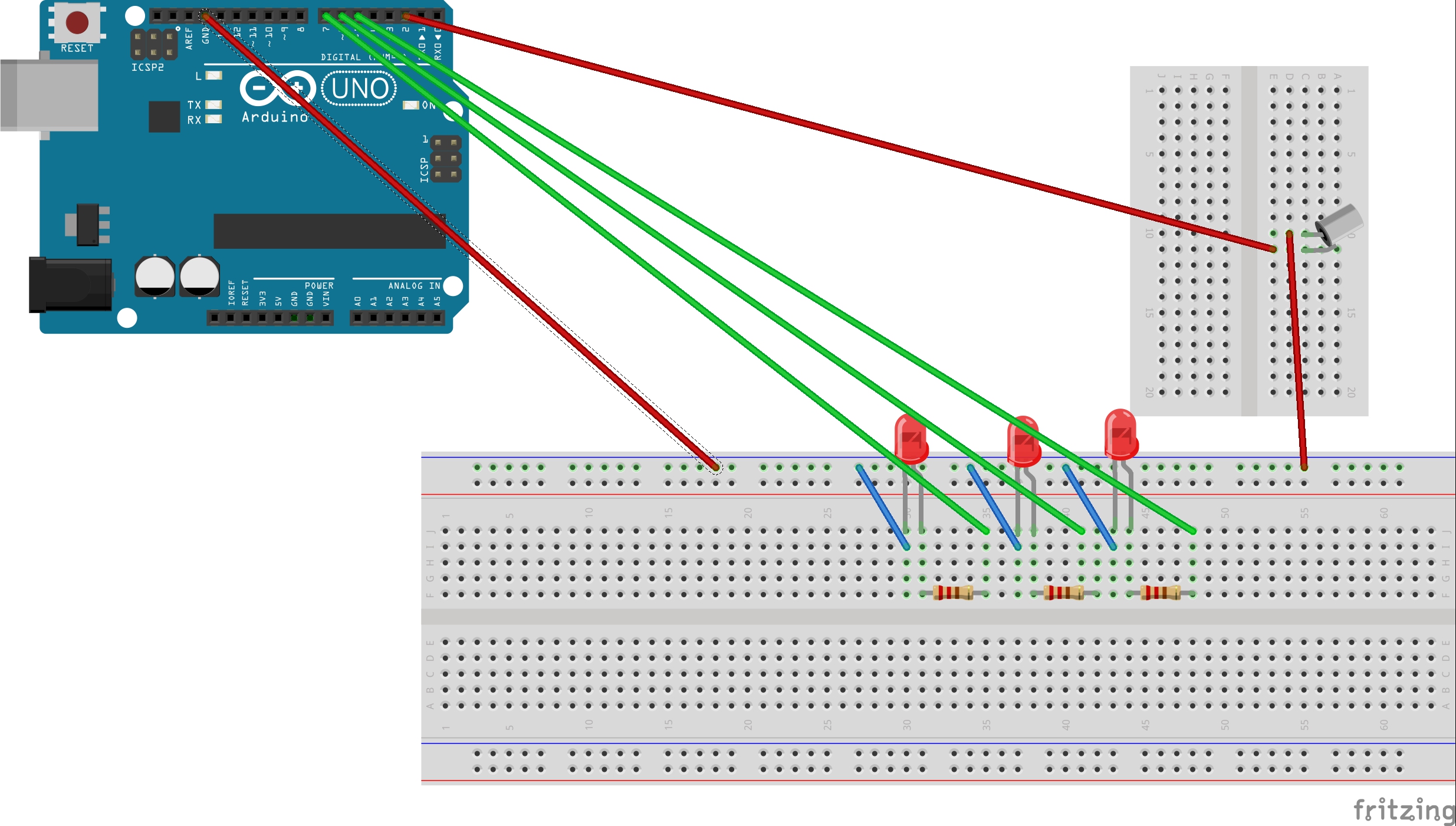
SchematicConnections:
Tilt Switch or Vibration Sensor
Long leg(anode) -> Pin 2 arduino
Small leg(cathode) -> breadboard negative rail
Arduino to leds
Pin 5 -> led 1 anode
Pin 6 -> led 2 anode
Pin 7 -> led 3 anode
LED s to breadboard
cathode 1 through 220 ohms to negative rail
Similarly for cathode 2 and cathode 3
Arduino to breadboard
Negative rail to GND
Code#define NO_SPECIAL 3
int l1=7;
int l2=6;
int l3=5;
int roll[]={NO_SPECIAL,4,1,6,5,2};//your very own secret sequence
int tiltSwitchpin=2;
int val;
int count;
int num;
The first definition is NO_SPECIAL standing for the first number to be initialized as the result. Note that this number will remain if no vibration is done.
then we have the definitions of the pins l1, l2, l3 which each represent one bit of the result from MSB to LSB.
int roll[] is THE MOST IMPORTANT variable here. This variable is not really a variable as it remains constant but this array defines the sequence in which the numbers will proceed after a vibration. As expected the first number is NO_SPECIAL. No member will be repeated.
Then we have the declarations of some global variables we will need during the code.
void setup()
{
 pinMode(tiltSwitchpin,INPUT_PULLUP);
 pinMode(l1,OUTPUT);
 pinMode(l2,OUTPUT);
 pinMode(l3,OUTPUT);
 count=0;
}
This function begins the program. Here we define the tiltSwitchpin as INPUT_PULLUP, which essentially is just a type of INPUT, but NOT the same!
We also define the led pins as OUTPUT.
void loop()
{
 val=digitalRead(tiltSwitchpin);
 if(val==HIGH)   {
   pulseIn(tiltSwitchpin,LOW);
   dice();
 }
}
This function runs repeatedly and is the equivalent of main() in Windows systems.
digitalRead() will read the incoming value on tiltSwitchpin and interpret is as HIGH or LOW.
If the value is HIGH, we wait till the value incoming is LOW( using pulseIn() !!note that this usage is not the usual usage of pulseIn()!!) and then use a function dice(), which is defined as:
void dice(){
 if(count>5)
   count=0;
 num=roll[count];
 count++;
 results();
 return;
}
There is nothing to explain about this code except the usage of results() defined as:
void results(){
 int b1,b2,b3;
 int temp;
 temp=num;
 b3=temp%2;
 temp/=2;
 b2=temp%2;
temp/=2;
 b1=temp%2;
digitalWrite(l3,b3);
digitalWrite(l2,b2);
digitalWrite(l1,b1);
 return;
}
Here we use dec2bin algorithm to obtain the bits b1, b2, b3 respectively representing the MSB to LSB(b1 to b3).
After that we digitalWrite() the values of each bit to the leds. Depending on whether the bits provided are HIGH or LOW, the leds will glow, thus representing the binary value of the dice result.
That's it!! Upload the code and shake the "dice" to get the results!
Thank you for reading this article :)

Comments
Please log in or sign up to comment.