In this project I'm going to tell you about how to use Over-the-Air (OTA) software update for NodeMCU (ESP8266). So In this case we are taking a project as we have previously explained named "Wireless Attendance System Using Wi-Fi (ESP8266) with MySQL". You can get the details here.
So what actually I'm going to do here, suppose I've installed this system somewhere in a office for attendance of employees or may be in school for attendance of student, now if I need to add more employees or student then what I'll do I'll take the NodeMCU and edit the code from system. So this will be a huge problem, as I don't want to mess up with these things like take out the NodeMCU and connect to laptop or PC and update the code. So what is the solution? Here is the solution and that is we can update the code Over-the-Air(OTA) without even touching the NodeMCU. So this is really a cool thing. So here I'll tell you how we can update the code Over-the-Air.
Installation of All Softwarea) Installation of LAMP Server and PHPMYADMIN: First of all let us clear one thing that we are using LAMP Server for this project. In case if you don't know what is LAMP, it is an abbreviation of Linux, Apache, MySQL and PHP. So if you have windows or may be MAC then you have to install WAMP and MAMP respectively.
So what we are explaining that is only for LAMP server: and here are the steps for installing LAMP server.
- Install Apache
sudo apt-get install apache2
- Install MySQL:
sudo apt-get install mysql-server
- Install PHP:
sudo apt-get install php5 libapache2-mod-php5
- Restart Server:
sudo /etc/init.d/apache2 restart
- Check Apache http://localhost/ if you install these steps successfully then you will get the apache page like the image below.
Here we are using PHPMYADMIN that is the web interface of MySQL so for that you have to install that also and the command for that is:
sudo apt-get install phpmyadmin
b) Installation of Arduino IDE:
You can download the latest Arduino IDE from this link.
Component Used:As for OTA update we have chosen rfid access code, you can chose other program code as well.
So for this project you need:
- Node MCU V3
- RFID RC522 Reader with Tag
- Jumper Wire
1) NodeMCU V3: NodeMCU is an open source IOT platform. It includes firmware which runs on the ESP8266 Wi- Fi SoC from hardware which is based on the ESP-12 module. The term "Node MCU" by default refers to the firmware rather than the dev kits.
2) RFID RC522 Reader with Tag: There are cheap RFID modules that can read and write Mifare's tags and being sold at several web stores, like eBay and included with many "starter kits" nowadays. Simply search RFID-RC522 (MF-RC522). The microcontroller and card reader uses SPI for communication (chip supports I2C and UART protocols but not implemented on library). The card reader and the tags communicate using a 13.56MHz electromagnetic field.
- Step1: Firstly open the Arduino IDE.
- Step2: Go to the File then click on preferences tab like Figure 1. Now you have to copy in the additional board manager URL- http://arduino.esp8266.com/stable/package_esp8266... then click ok.
- Step 3: Now go to the Tools then select Board Manager. Open window like figure 2. Just Scroll down on that window and search for ESP8266 by ESP8266 Community and then click on install button.
- Step4: Restart your Arduino IDE
- Step5: Now go to Tools then Select like figure 3.
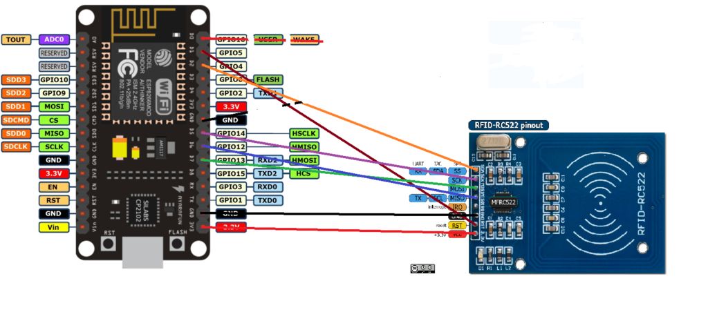
Circuit Diagram of this project is given below. Here are the connections of our circuit:
RFID-RC522NODE MCU
- SDA(SS)-------------------------GPIO2---------D4
- MOSI ----------------------------GPIO13--------D7
- MISO ----------------------------GPIO12--------D6
- SCK ----------------------------- GPIO14--------D5
- GND -----------------------------GND
- 3.3V ------------------------------3.3V
- RST ------------------------------not connected
- IRQ -------------------------------not connected
Here we are using RFID RC522. So you have to import MFRC522. Here is a GitHub link.
Why We Need MQTTHere we don't necessarily need MQTT. What is the purpose of MQTT here that we want to make one toggle button in this case. So when it will be 0 then our NodeMCU will be in programming mode and if it is 1 then it will be in OTA mode. So if you want to update the installed NodeMCU just click the button and value will be 1, So here you can update the code and then after successful update you can again click and make it 0 for programming mode.
If you don't want to go with MQTT then you can chose one push button as well which is connected to one gpio of NodeMCU, but again the problem is that button will always be there connected to NodeMCU, and also every time you need to press that button for making it OTA or programming mode.
So That's why we thought that we should go with some soft toggle button and we can easily make that using MQTT.
In this step I'm going to explain you about how we can create Mqtt Dashboard. So for that we are using Adafruit Mqtt. The UI of Adafruit IO is very user-friendly. So Step by step I'm going to explain you about this. So you just follow the process.
Here are the steps:
1. First you need to create account in io.adafruit.com
2. You will get the page like below, so fill these details, now when you will sign in you will get the page like below
3. In this page in the top right corner you will get some icons. From this you can click on 'Create a new block'. So from here you can create toggle button.
As we have given the name Bulb1 for our toggle button. When you will create that button then you need to give value 1 and 0 for for High and Low respectively, remember these values are not a numeric value, these are string values which we will convert to integer through our Arduino Code.


Comments
Please log in or sign up to comment.