


Hardware components | ||||||
| × | 1 | ||||
_wzec989qrF.jpg?auto=compress%2Cformat&w=48&h=48&fit=fill&bg=ffffff) |
| × | 1 | |||
| × | 1 | ||||
| × | 1 | ||||
| × | 1 | ||||
| × | 1 | ||||
| × | 1 | ||||
| × | 1 | ||||
Software apps and online services | ||||||
| ||||||
| ||||||
Hand tools and fabrication machines | ||||||
| ||||||
I am in the process of making a Power Unit for my MG F car, where I am manually machining out the parts on a hobby milling machine at home and around my day job. I will be sharing the MG F project on here once it gets fully going too.
To save my aching feet and arms every evening after work, I am now looking at converting it to CNC.
I first got introduced to O-Drive by James Bruton on his OpenDog project.
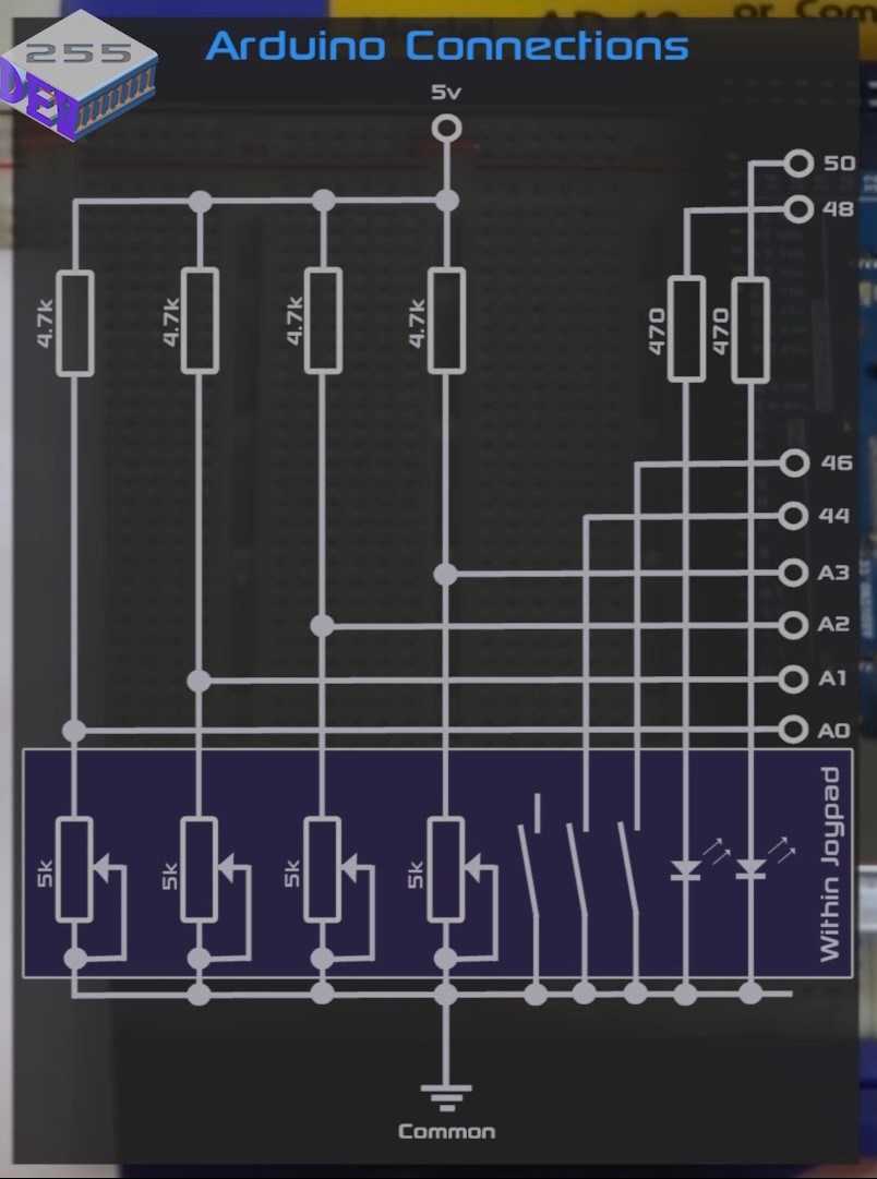
I’m using Alibre Design for CAD and Fusion 360 for CAM (G-Code generation). The Arduino Mega directly controls the ODrive Brushless DC motor controller and temporarily uses a joypad (from an old indoor helicopter) to manually control the mill.
I have successfully machined out components using the manual Joypad control using the converted Y-axis; where I made this first to setup and test all the controls and write the sketch.
I will be writing my own G-Code sketch at some point in the near future and sharing it all here, on my website and/or on GitHub; along with all the CAD files for the mill conversion.
The machine is an Axminster Sieg x1 that I bought 10 years ago.
Here are some links for my project on other sites: -
ODrive Brushless DC Controller Blog
And some pictures: -
I hope you enjoy watching this project as much as me making and developing it.
Please feel free to suggest any content or want to know more, I am happy to answer questions as I want to help others understand the whole process (including what doesn't go too well).
Update 21/05/2020
Here is part 7 & 8, where part 8 goes through some of the sketch to control some aspects required, such as how the keypad functions and how to compensate for backlash. Also, I try to explain what backlash is and why you need to account for it.
I hope you are all enjoying this project and working on your own ideas.


_t9PF3orMPd.png?auto=compress%2Cformat&w=40&h=40&fit=fillmax&bg=fff&dpr=2)
Comments
Please log in or sign up to comment.