


Hardware components | ||||||
_ztBMuBhMHo.jpg?auto=compress%2Cformat&w=48&h=48&fit=fill&bg=ffffff) |
| × | 1 | |||
 |
| × | 1 | |||
 |
| × | 1 | |||
 |
| × | 1 | |||
Hand tools and fabrication machines | ||||||
| ||||||
The first Pardon Me For Interrupting sketch and circuit showed how to set up a precision timing interval using timer interrupts. This tutorial will show how the timing interval can be synced to an external input input using pin change interrupts. The examples shown are of two synchronized flashing LEDs, but the theory can be easily expanded to applications that read asynchronous serial input framed with start and stop bits.
My MotivationIf you've worked through part one, you might recall my reason for learning about interrupts was to see if I could improve upon the SoftwareSerial library and build a full-duplex capable sketch. My hope is to one day connect a cluster of Raspberry Pi 3.3V serial consoles to a custom 3.3V ATmega328-based terminal server.
But, before that project starts, I've got my sights set on a full-duplex loopback proof of concept using an Arduino Uno to talk to itself. This tutorial gets me one step closer to my goal.
The Arduino UNO used in this tutorial is a 5V device. Raspberry Pi is a 3.3V device. Never connect the two of them without some sort of level shifting.Review of Part One
The first tutorial was a simple example of two LEDs blinking -- the built-in LED and one external LED. The flashing for the built-in was done with timer interrupts and the external LED was flashed with the traditional delay() subroutines.
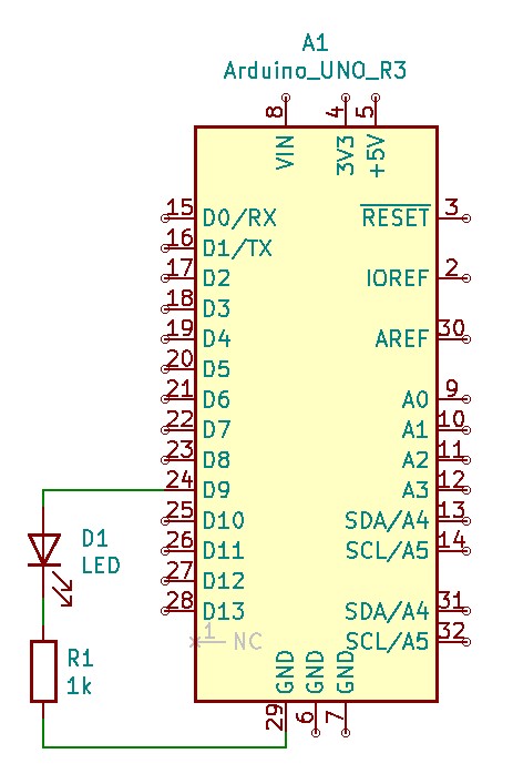
The schematic it extremely simple and looks like this:
And the sketch looks like this:
#define LED 9
void setup() {
 pinMode(LED_BUILTIN, OUTPUT);
 pinMode(LED, OUTPUT);
 cli();
 TCCR1A = B00000000;
 TCCR1B = B00001100;
 TIMSK1 = B00000010;
 OCR1A = 31250;
 sei();
}
void loop() {
 digitalWrite(LED, LOW);
 delay(500);
 digitalWrite(LED, HIGH);
 delay(500);
}
ISR(TIMER1_COMPA_vect)
{
 PORTB ^= B00100000;
}
In the sketch, the setup() subroutine was tasked with configuration of LED pin modes and enabling the ATmega328's timer1 to interrupt every half second. The interrupt service routine (ISR) simply toggled the value of pin D13 to flash the built-in LED, while the loop() subroutine blinked the external LED on pin D9 the old-fashioned way using delay().
Together, both LEDs flashed in unison. At least for a while. There was noticeable drift after a few hours of operation. But, it proved the point of using timer interrupts for executing a regular, periodic task.
AProblemofTiming
My ultimate goal is to communicate with a remote device (the Raspberry Pi) at 9600 baud. But, because of the ATmega's 16MHz clock crystal, the closest I'm ever going to get is 9598 baud (because 16MHz just isn't evenly divisible by 9600.)
9598 is close enough to accurately receive short bursts of incoming data, but after a while timing will start to drift, just like the two LEDs in part one became less synchronized over time. Without some way to keep the input subroutine in sync with the data coming in, it won't be long before the Arduino is going to start mistaking one bit for another and the incoming data will be full of errors.
Granted, with only 0.02% of error (9598 vs. 9600 baud) this drift is going to take hours, not minutes.
Fortunately, the problem of serial data synchronization was solved long ago with the inclusion of start bits and stop bits. Take a look at the diagram below.
The illustration shows how bits are communicated serially from one device to another. The key thing to note is the inclusion of two extra bits -- the start bit and the stop bit.
Before any data is sent, there is always one start bit, a low signal. After the data bits are sent, there is one stop bit, a high signal. During times when no data is being sent, the line is held high, like one long stop bit (shown as idle in the diagram.)
With the stop bit always high and the start bit always low, there is a guaranteed transition from high to low before any byte of data sent over the wire. If the ATmega328 can detect that voltage transition and use it to synchronize the timer interrupts, any problem of drift will be solved and the data byte can be read accurately.
This method of synchronizing serial data is nothing new. Hardware-based UARTs often use phase-locked loops (PLLs) to correct any drift in timing frequency. (Wikipedia has an excellent article explaining the details of PLLs.) This software sketch uses a similar, but simplified method to keep things in sync.
PinChange InterruptstotheRescue
Timer interrupts aren't the only interrupts the ATmega328 can respond to. It can also detect changes on input pins and execute an interrupt service routine (ISR) in response.
In the picture above, imagine the three gentlemen on the bench are waiting on a train. They all have watches, but they're the old wind-up variety. Maybe one runs a little fast, while another runs a little slow. To make matters more interesting, a dandy in a top hat stops by to chat incessantly, making them forget about checking their watches.
Soon, they've lost track of time. How are they ever going to know when their train is ready to depart? Fortunately for them, the train conductor blows a whistle and shouts, "All aboard!"
The men on the bench know the train is leaving. They might even take the time to adjust their watches, because whatever time the conductor has on his watch is the time used for the train schedule.
Using pin change interrupts to synchronize the timer interrupt works on a similar principle.
How Does It WorkontheATMega328?
Take a look at the diagram of data being set as a serial bit stream again.
Notice how the start and stop bits are marked in the center of the area where they occur. Measuring from the middle makes good sense. Even if the incoming data is not perfectly aligned to where the boundary is expected, the value read will still be correct. Trying to measure at the extreme left or right side could result in the previous or next bit being read by mistake.
Serial data rule number one: always read from the middle.
This means the timer interrupt should always be occurring right in the center of the start, stop or data bit boundaries. In terms of the timer count value, that's when it reaches the number stored in the timer's output compare register OCR1A, triggers an interrupt, and resets the timer to zero.
When pin change interrupts are configured, they will always occur at the beginning of the start bit and the beginning of any data bit that transitions from zero to one or one to zero. But, the interrupt will always be at a bit boundary, never in the middle.
Here's an illustration with the familiar serial bit stream, but zoomed in on a single byte of data.
The longer red lines between digits show where pin change interrupts will potentially happen. It's guarantied there will be a pin change at the start bit / stop bit transition. There are also potential pin changes in the data bits. For example, an ASCII letter A is 01000001 in binary. There will be 3 additional pin changes: zero to one, one to zero, and zero to one.
The yellow sawtooth pattern running over the top is a representation of the timer count. Reaching maximum count will reset the timer to zero and trigger an interrupt. Those interrupts need to occur in the center of the bits for the best chance of reading good data.
Obviously, the pin change and timer interrupts are not aligned. Keeping the timer in sync with an incoming data stream will not be as simple as resetting the counter to zero whenever a pin change occurs. But, it's not much more difficult either.
Look at the timer value during the pin changes. It's half way through its count. If things are in sync, the timer count will be exactly half of its maximum value whenever a pin change occurs. If it's not at half the maximum value, then setting it to that number will correct any drift in synchronization.
It's that easy. In fact, there's no reason to even do a comparison between actual and ideal timer counts to see if things are in sync. Every time there's a pin change, set the timer value to half its maximum and return. That's all the pin change interrupt routine has to do.
With only nine bits between each guarantied start bit / stop bit transition, there's not much opportunity for the timer interrupts to get out of sync. And that makes the interrupt service routine very short.
Here's the ISR:
// Interrupt handler for pin change.
ISR(PCINT2_vect)
{
 TCNT1 = OCR1A >> 1;
}
TCNT1 is the timer1 count register. It holds the current count. OCR1A is the output compare register. It holds the maximum value that triggers a timer reset and timer interrupt. The >> 1 is a bit shift operation. It shifts the value of OCR1A one bit to the right which, in binary, is the same as division by two.
Any time the pin change interrupt is triggered by a high-low or low-high transition, the counter is reset to half its maximum value. By the time the counter finishes counting to the maximum value, it will be right in the middle of the next bit, precisely where it needs to be for the most accurate reading.
Of course, the ATmega328 has to be set up to allow pin change interrupts. The code to do that needs to be added to the setup() routine, and looks like this:
 PCICR = B00000100;
 PCMSK2 = B10000000;
The first instruction enables the interrupts for Arduino Uno pins D0..D7. A change on any of these inputs will cause an interrupt. But, the second instruction sets a mask to make INT23 (Arduino Uno pin D7) the only one that gets through. Anything happening on D0..D6 is ignored.
Interrupt Blink, Part DeuxPutting it all together with the code from the first interrupt blinking tutorial looks like this:
#define LED 9
#define BUTTON 7
void setup() {
 Serial.begin(9600);
 pinMode(LED_BUILTIN, OUTPUT);
 digitalWrite(LED_BUILTIN, HIGH);
 pinMode(LED, OUTPUT);
 pinMode(BUTTON, INPUT_PULLUP);
 cli();
 TCCR1A = B00000000;
 TCCR1B = B00001100;
 TIMSK1 = B00000010;
 OCR1A = 62500;
 PCICR = B00000100;
 PCMSK2 = B10000000;
 sei();
}
void loop() {
 digitalWrite(LED, LOW);
 delay(1000);
 digitalWrite(LED, HIGH);
 delay(1000);
}
// Interrupt handler for timer match.
ISR(TIMER1_COMPA_vect)
{
  PORTB ^= B00100000;  // Toggle bit 5, which maps to pin13.
}
// Interrupt handler for pin change.
ISR(PCINT2_vect)
{
 TCNT1 = OCR1A >> 1;
}
The code shown above will flash two LEDs as a proof of concept on synchronizing the timer to an external interrupt. One LED uses the delay() method while the other uses timer interrupts. Pin 7 is used to simulate an input signal.
The speed is much, much slower than the 9600 baud needed for my terminal server project. The human eye couldn't see it otherwise. But, once I'm sure it works, a change of the timer1 prescaler and output compare register is all it will take to speed it up.
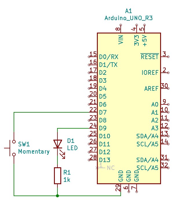
Here's the schematic for the wiring of the LED on pin 9 and momentary push-button switch on pin 7.
Pressing the button (SW1) will cause a high to low transition on the input pin (just like the stop bit / start bit transition.) Press it and watch the built-in LED sync itself to the new timing. If you don't have a button, just attach pin 7 to ground momentarily with a piece of wire.
Pressing the button at various times will cause the two flashing LEDs to get closer to synchronizing or farther apart. It all depends on how precise you are with your presses. But, eventually the LEDs will drift out of sync, unless you keep pressing the button at precise and regular intervals.
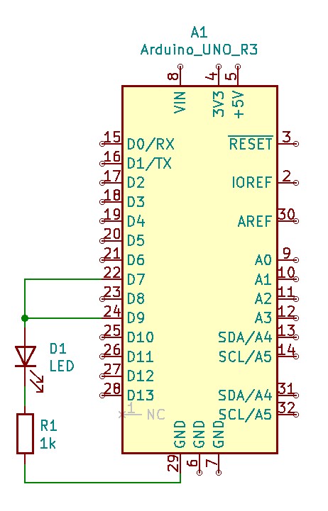
Automatic SyncAnother way to approach the input signal is to let the pin driving the external LED supply it. Remember, the pin 9 LED flashes the external LED based on the delay() function. It's running completely independent of the built-in LED's flashing. Even though they're running on the same Arduino, pin 9 can be thought of as an output from a remote device.
Pin 7 can be thought of as the input tasked with listening to the remote device. Output is routed to input. Attaching pin D7 to Pin D9 is all it takes to set this up.
Now the pin change controlled by the delay() subroutines is supplying a simulated input signal as well as flashing the external LED. Watch what happens. You might see a brief out of sync display for the first flash, but after that the two will be in sync.
It's not simultaneous flashing like the previous tutorial, but it is in sync nonetheless. Watch and you will see a pattern something like this:
- External LED on and built-in LED off.
- Both LEDs on.
- External LED off and built-in LED on.
- Both LEDs off.
This pattern will repeat for as long as the Arduino remains powered. Unlike the previous tutorial, the sequence of flashing will not drift apart over time. Let it run overnight and you'll see the same pattern in the morning.
Remember the serial bit timing illustration from earlier? It looks like this:
What the LEDs are showing is the pin change interrupts (external LED) and the timer interrupts (built-in LED). Watch the display carefully. Notice how the built-in LED's transition always happens in the middle of the external LED's transition. They are in perfect synchronization, but out of phase.
And, because the built-in LED represents the timer count, it shows that a sample of the input (the external LED) would be taken at the center of the bit each time. All I need to do is speed the whole thing up and I'm well on my way to accurately reading serial data at 9600 baud.
Next StepsBlinking LEDs is fun, but what about my Raspberry Pi terminal server project? That's what got me started on interrupts in the first place. Well, here's what I'm planning to do next:
- Modify the timer ISR. Instead of toggling an LED, read an incoming bit.
- Replace the loop() routine with something that sends a character from USB input to a remote machine.
- Make the input and output pins selectable to attach to any one of a number of Rx/Tx pairs.
- Buffer the input.
- Move the incoming signals to the D8..D13 pins, because they have a very high interrupt priority (higher than the D0..D7 group and any of the analog pins.)
- Create a way to select between various transmit and receive pairs of pins to attach multiple remote hosts.
That's all I can think of now. Maybe once that's all done I'll get fancy and use the analog ports for tracking temperature, or voltage and current statistics, or both. But that's far off on the horizon. For now, I'm happy I've got two LEDs blinking in a self-correcting interrupt-driven timing loop.


Comments
Please log in or sign up to comment.