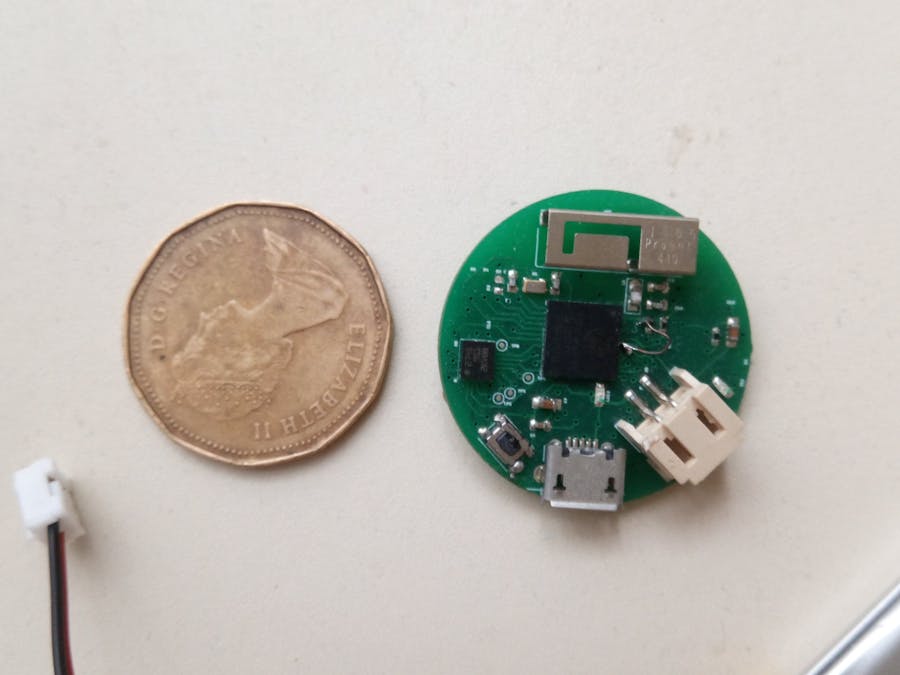
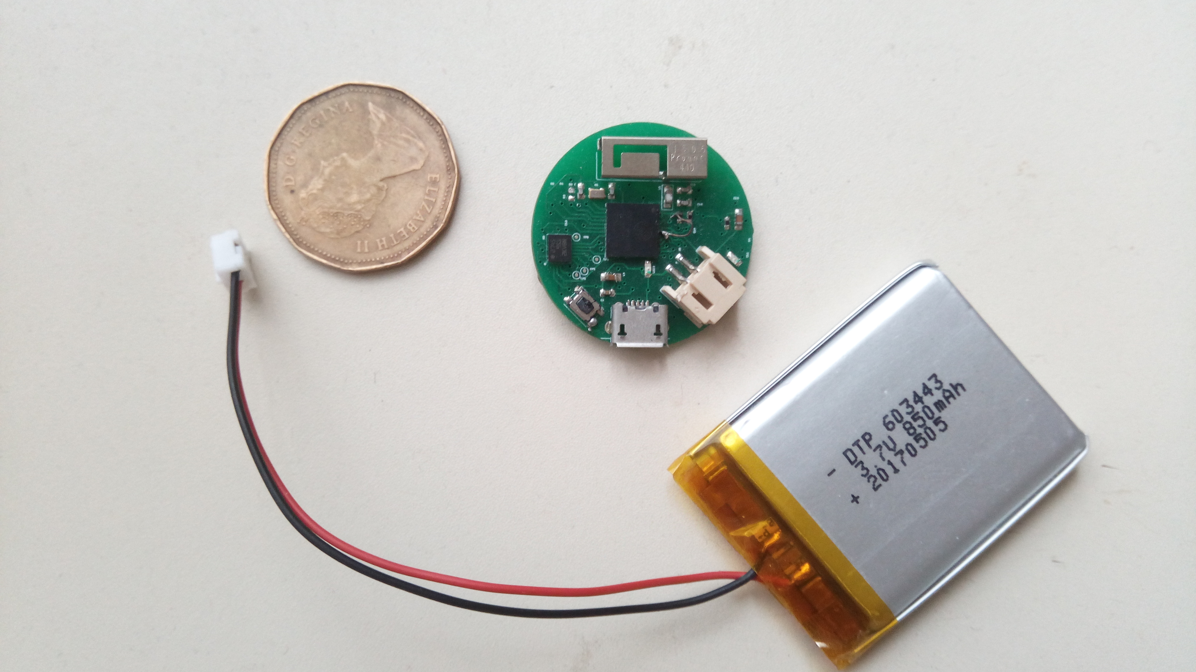
A while ago I designed an ESP32 PICO D4 board coupled together with an IMU on a small PCB the size of a coin cell. The initial idea was to build a small WIFI enabled dev-board to send accelerometer and magnetometer data wirelessly via WIFI. The data would then be used to feed an AI (Long Short Term Memory (LSTM)) Deep neural network in order to trigger actions. The AI runs on the local laptop server while the ESP32 is only responsible for sending the data via WIFI. While the LSTM can run on the ESP32 for a standalone solution it would require some fine-tuning of the C code to determine what is possible with the limited LIPO power budget.
Below we'll go through the hardware design decisions and the software tests that were implemented to bring the board to life.
The ESP32 PiCO D4 board was tested with the LED WIFi server. After some hardware troubleshooting and firmware debugging , the design works. The first thing was to program a blinky Arduino program that toggles the LED pin once every second.
The hardware design was then tested by gathering and analyze accelerometer and magnetometer data for AI and machine learning.
Hardware designThe initial requirements were to design a board that had the following features:
a) a WIFI System in Package (SIP) MCU
a) embedded programmer so that we can program the board on the go
b) Efficient PMU (Power management unit) for maximum batter life
c) Battery charging for LIPO and LED indicator
d) Accelerometer, Gyro and magnetometer inertial measurement unit (IMU) sensor to recognize events and trasmit them via WIFI
SIP & WIFI Antenna
The reference design for the ESP PICO D4 was followed closely. A 3D antenna from ProAnt was used. A PCB trace antenna could have been cheaper but the selected 3D antenna has better power output.
LED
Two LEDs are on board. one is used when the USB is plugged in. This starts charging the LIPO. The other is used as an indicator connected directly to a GPIO.
IMU
I used an LSM9DS1 IMU which is composed of a accelerometer , gyroscope and magnetometer MEMS sensors in a low power QFN package.
Serial Programming
1. The serial programmer was based on a CP2102N from Silabs included on the board to facilitate programming and transmission of data during testing.
The board was designed with a 4 layer stackup using Eagle Cad. Some design decisions were made as following:
Power management Unit
1. A LIPO batter was selected to accommodate different power budgets. The selected battery I used was a 400 mAhr LIPO. This can be bumped up to 4000mAhr if needed. The board was smaller than the battery I used to test.
2. The board uses an MCP7831 LIPO battery charger. While not the fastest charger around (500mAhr) it is quite easy to solder by hand.
3. An LDO (Low drop Out regulator) was used to power up both the WIFI MCU and the sensor. The current budget of the LDO should be more than 500mA since for small duty cycles the current draw is greater than 500mA. An 800 mA LDO was used. The current draw from the IMU sensor is negligible at 50 mA under maximum data throughput. implementing a switcher could have introduced problems with the WIFI due to EMI.
The circuit is implemented in such a way so that when the USB is plugged it will power the board and the LIPO will be charged.
The BOM is shown below:
Errata
Two issues were the lack of a ground plane and forgetting to wire one of the control pins. The lack of GND plane result in the board dissipating quite a bit of heat during WIFI transactions. The other issue was fixed by some fine surgery.
The first issue was I missed the pull-up from SW1 IO0 to VDD. The fix was to solder a 10k manually.The second issue was removing the pull-up from IO12.
I did not put an inline resistor on TXD as per datasheet recommendation but this did not make a difference in the end. The pic below shows the baord layout.
As mentioned , the layout was done in Eagle using a 4 layer stack-up.
Software designThe first step was to plug in the board and test programming it via ESP SDK. This was where the PicoD4 got stock into the boot loop.
To fix this I had to:
1. Remove Pull-up from IO12 , R5.
2. Change R6 from 10 K to 0 ohm. .
3. Tombstone a 10k resistor on IO0 of push-button and hook a fly-wire to VDD to enable reset.
This fixed the bootloop and now I could read the fuses and the chipset revision. Apparently the chips I bought were rev1.
I ended up using an Arduino LSM9DS1 library to get the IMU to output data via the serial output. The schematics were wired so that the Sensor could be configured either using SPI or I2C depending on which pullups are populated.
I used the following two Arduino Libraries for the sensor:
https://github.com/adafruit/Adafruit_LSM9DS1
https://github.com/sparkfun/SparkFun_LSM9DS1_Arduino_Library
The packet encapsulates accelerometer, gyro, magnetomer , RRSI, and temperature and time stamp or packet index data although these are at the user discretion.
To get the RSSI use the
WiFi.RSSI();
Data can be packed in binary or JSON-nified and de-capsulated on the server side via a Python script.
At the moment I paused development of the transfer protocol in order to test this the gesture recognition via serial port. This still works sine it does not inhibit any deegrees of freedom.
AI gesture tracker
The hole purpose of this project was to implement an AI WIFI gesture tracker (that's a mouthful by the way).
This will make it possible to attach the node to a glove and recognize Harry Poter like spells which can trigger actions triggered via a REST API.
To implement this I decided to send the data to a HTTP Python server so that it processes and outputs the predictions from a recurrent neural network.
For the AI gesture recognition an LSTM open source code was used from:
and
https://github.com/guillaume-chevalier/LSTM-Human-Activity-Recognition
The most time consuming part here is saving a lot of training data and labeling it. To recognize the above gestures for each "spell" one has to save an array of 125 data points multiple time.
Since the scope of this project is a bit large, ( one can do a Ph.D thesis on it) this part leaves room for a lot of experimentation so it's still ongoing.
Schematics and code snippets used for testing are attached and uploaded in repo.
Since this project is still ongoing it may be updated in the future. Here we showed hot to build form scratch a wireless badge the size of a coin cell.
Planned revisions may:
a) add a microphone to do 'beam me up Scotty" kind of communication
b) bring out unused pins to a header
c) implement lightweight LSTM variations on ESP32.


Comments