A GPS tracker logger is a device that records GPS data. It can be used for tracking assets, monitoring position of pets, people, cars... you name it.
It can also be used for fun outdoor activity such as hiking or geo-caching. Normally a GPS tracker is fairly small and low power. The MAX32620 dev-board from Maxim is a nifty low power ARM MPU board which is tailor made for wearable devices. I thought it would be a good project to build a small GPS logger with a TFT display.
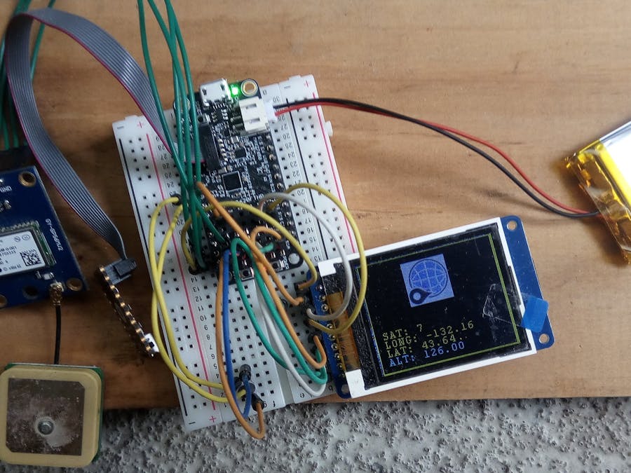
The hardware is composed of the MAX32620FTHR development board, a UBlox-6 GPS module, an 1.8 inch TFT screen as well as the MAX77650 programmable LIPO charger/regulator and the MAX17055 LIPO fuel gauge.
The Ublox-6 GPS module is connected via the serial interface to the MAX32620FTHR. The ST7735 display is connected via the SPI0 bus. An SD card was also used for data logging. The SD card makes use of the same SPI bus but uses a different chip select.
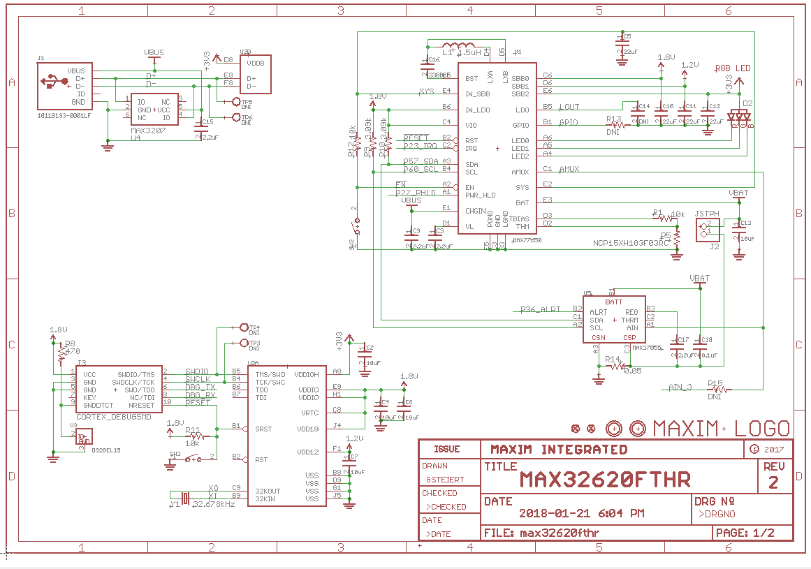
The MAX77650 LIPO charger provides the power for the MCU and charging for the LIPO battery. The MAX17055 Fuel gauge purpose is to query the battery and provide a status of the State of Charge including voltage, current and battery temperature.
The connection to the board pinout diagram are as follows:
GPS is connected to UART2 pins, TX and RX.
TFT is connected to follwoing PMOD connector pins:
- LITE -> VDD,
- MISO to P1_0
- MOSI to P1_1
- TFT_CS to P1_3
- SCK to P1_0
I used mbed framework to implement the firmware. Basically the MAX32620FTHR queries the GPS every second and updates the TFT display with the data in real time. Since this is a low power solution intended to last for a long time the MCU shuts down the TFT display after 15 seconds.
Initially I tried to use a pass-through bridge to stream data to the PC. I found that the Mbed framework has an issue when two UART are executed so the debug serial would not work simultaneously with the GPS serial.I then piped the GPS data to the TFT display and it worked.
Next a timer was used to provide timestamp functionality for the data-logging option. When the GPS tracker is powered on a new file is opened on the SD card and the GPS data is continuously written. The SD filesystem library was used to add data-loggin capability to the GPS tracker.
The solution makes also use of the MAX fuel gauge which gives the LIPO battery voltage, temperature and current consumption. The hardware also uses the SIMO buck regulator.To display images on the TFT display I downloaded the image as a JPEG file.
Then I used FSResizer http://www.faststone.org/FSResizerDetail.htm
to resize the image to 50x50 pixels. The next step was converting the image to an array to display it on the TFT display.
For this task I used lcd-image-converter-20161012. Since each pixel is 16 bit select the RGB 565 scheme.
The image is then exported from file convert. Now the image is included as a header file on the main application file.
The main application initializes the TFT display, configures the LIPO charger to output 3.3V and disables the LDO, next the fuel gauge is configured using a sense resistor to 50mohm.
The main program loop constantly queries the satellites in view when the GPS acquires a lock and updates the TFT display every 4 seconds.
The TFT display alternates between showing the battery status with battery current and voltage.
Notice that when the programmer and the USB is unplugged the board consumes energy so the current is negative. When the board is plugged in the current consumption is positive which means the board is being charged.T
Project CodeThe project code is uploaded under this page:
https://os.mbed.com/users/DimiterK/code/MAX32620FTHR_GPS_Tracker/
So this shows how to quickly prototype a low power GPS tracker/logger with the MAX32620FTHR board. Obviously you can add a bunch of features to this app. Make it so, number 13.


_1x_bGT19vVAby.png?auto=compress%2Cformat&w=40&h=40&fit=fillmax&bg=fff&dpr=2)
Comments
Please log in or sign up to comment.