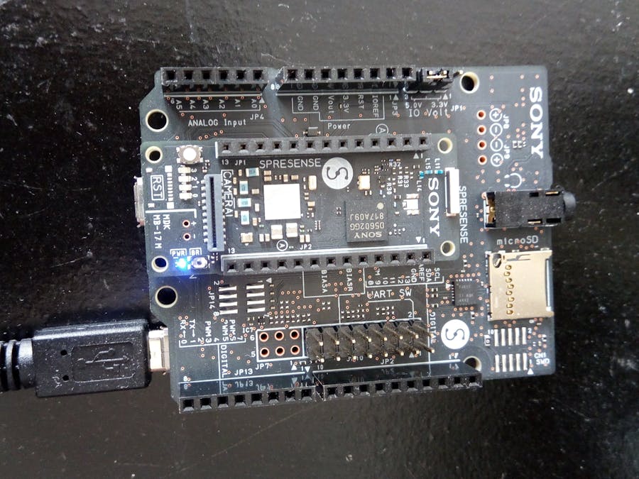
This project will implement a GPS WiFi camera system using a multi microcontroller architecture based on Sony's Spresense board and ESP32 WiFi MCU.
The Sony Spresense contains an embedded GPS. It comes with 6 MCU cores. The Spresense will be responsible for interfacing with an ultrasonic distance sensor and parsing the GPS data (i.e serving as a gnss tracker). The idea is that when the distance sensor is below a threshold the GPS data will be recorded and a live video is enables by sending a command to the ESP32 MCU.
The ESP32 will interface with a camera and provide a live video feed via a browser. The ESP32 will also interface with a 1.8 inch TFT display.
Camera subsystemTo implement the ESP32 camera an OV7670 camera module was used. The OV7670 was configured to operate in QCIF resolution mode. This is a scaled down resolution from VGA mode. The decoded camera data is then piped directly to a 1.8 inch TFT display with an ST7735 controller. The camera is configured via two pins using the SCCB protocol which is very similiar to OneWire (i2C).
The TFT is connected to the SPI bus. The test above verified the correct working of the camera and TFT display.
The next step was to test the WiFi functionality.
To test this on the first line, enter your WiFi network name and password.
#define ssid1        "YOUR_WIFI_SSID"
#define password1    "YOUR_PASSWORD"
The un-comment the lines:
 //camera->oneFrame();
 //serve();
 //displayRGB565(camera->frame, camera->xres, camera->yres);
Now open a browser and type the IP of the camera. You'll see a live video stream from the ESP32.
Next step was modifying the code again to enable WiFi transmission if a flag is set. The flag is received from the Spresense. If a command a serial is received, the unit enables the transmission of the video frames via WiFi to a browser.
GPS subsystemThe system makes use of the Spresense GPS sample app. Specifically I'm using the GNSS tracker. This requires using an SD card in conjunction with the baseboard.
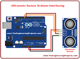
A HCSR-04 is used as a distance sensor. This is an ultrasonic sensor which measures distances by measuring the length of the received echo.
The code below was used to test the operation:
// defines pins numbers
const int trigPin = 2;
const int echoPin = 5;
// defines variables
long duration;
int distance;
void setup() {
pinMode(trigPin, OUTPUT); // Sets the trigPin as an Output
pinMode(echoPin, INPUT); // Sets the echoPin as an Input
Serial.begin(9600); // Starts the serial communication
}
void loop() {
// Clears the trigPin
digitalWrite(trigPin, LOW);
delayMicroseconds(2);
// Sets the trigPin on HIGH state for 10 micro seconds
digitalWrite(trigPin, HIGH);
delayMicroseconds(10);
digitalWrite(trigPin, LOW);
// Reads the echoPin, returns the sound wave travel time in microseconds
duration = pulseIn(echoPin, HIGH);
// Calculating the distance
distance= duration*0.034/2;
// Prints the distance on the Serial Monitor
Serial.print("Distance: ");
Serial.println(distance);
}
Add voice interaction. Keyword recognition and audio feedback.
Add AI capabilties from accelerometer data using LST network. This is a work in progress.


Comments
Please log in or sign up to comment.