Today in this article we will talk about how to make a basic Long Distance Transmission System circuit. Along these lines, let me give you a concise depiction of the circuit. How Generally this functions and How I am speaking to the things to you all with a portion of the straightforward parts accessible in our area. This is a simple circuit dependent on straightforward transistors and a few resistors.
Idea:Assume I need to control an engine with a switch. Along these lines, I will simply require an engine and a Switch. Also, The association will resemble this in the image. The Motor and the switch will be associated with the arrangement and from that point onward, The external terminals will be associated with mains Supply with 110V or 220V relying upon your nation. Here our objective is long-ago so what we can do is expand the switch wires.
Part Source:🔸 $0 for IATF Certification PCB Prototype (24 hours lead time): https://www.nextpcb.com/?code=creativec
🔸 Real PCB & PCBA Manufacturer Give You 10% Off: https://www.nextpcb.com/activity_thermometer?code=creativec
🔸 Learn more about PCB assembly: https://www.nextpcb.com/pcb-assembly-services?code=creativec
NextPCB is one of the most experienced PCB manufacturers in China and has 15 years of experience with UL & ISO9001 & ISO4001 Certified to ensure the PCB quality of your project. https://www.nextpcb.com/pcb-assembly-...
Problems:It is a simple circuit. Right? Presently there are a few blemishes of the circuit. Here I need to run High Loads like a Motor. So I should utilize high measure wires for associating with the switch. What's more, You comprehend what High Gauge wire isn't so modest They are over the top expensive.
What's more, another fundamental defect is the resistive misfortune. Let me let you know in detail. At the point when the range is expanding then the wire length is likewise expanding. So there will be a High resistive loss of the wire. Thus, these are 2 fundamental insufficiencies of the circuit.
Arrangement:For expelling every one of these misfortunes I just concocted this straightforward arrangement. I will make a straightforward circuit that will be associated with the heaping side. The circuit will simply take a sign for killing on/off the Motor.
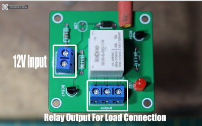
Watch YouTube Video:Schematics and Overview:Let me give you a basic diagram of the framework. This circuit depends on basic transistors. Here I have utilized LDR as a Light sensor and a Relay as a switch. The hand-off is an advanced switch that can deal with the greatest current.
On the off chance that the light falls on LDR, at that point the transfer is off. What's more, on the off chance that the LDR is in Dark, at that point the Relay will be on.
Here we will offer light to the LDR through an outer light source, for example, LED. Presently on the off chance that we turn On/Off, the drove, at that point, the Relay will be off/on. The LED takes a limit of 20mA of current So you can utilize any typical wire for controlling the LED.
Thus, here are the basic Schematics of the circuit. The LDR and the 2.2k resistor makes a voltage divider. From the outset, assume that the LDR isn't getting light. At that point, the resistance of the LDR will be boundless. In this way, not current will spill out of Q1 Transistor. This time current streams from Vcc to Q2 Transistor's Base through 1k Resistor. It Activates the Q2 Transistor. The Load which is associated with the Q2 Transistor will be controlled up.
Contrarily, on the off chance that the LDR Gets light, at that point the Q1 became conductive and every single current course through the briefest way that is VCC to GND 1k Resistor. No present will stream into the Q2 Transistor's Base. In this way, It won't trigger the Q2 Transistor just as the Relay.
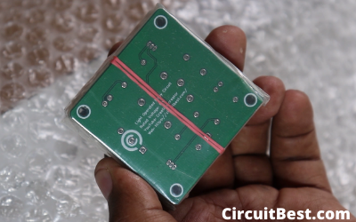
Circuit Complexity:Alright, Guys All things aside, I changed over the schematics to PCB and requested it from NextPCB.com. This is an extraordinary organization for Low Budget PCBs. They are giving probably the most inventive printed circuit sheets with the best guidelines. They offer 4 layers PCBs just for 28$
Simply Upload Your Garber document today. As of now, they are offering 100 by 100cm 10 PCBs for nothing to their New enrolled Customers. Handling time is 48 Hours and transportation time is likewise exceptionally Quick.
What's more, hold up Because of COVID-19, NextPCB is giving a restrictive 10% Discount on their PCBs and PCB Assembly Orders. so why you are hanging tight for? Put in your first request from NextPCB.com.
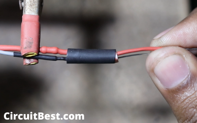
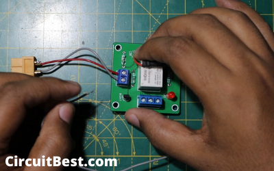
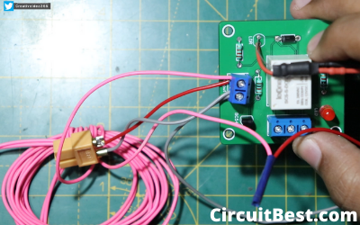
Testing:For testing, I utilized light as a heap. In this way, I associated the Holder wires with the hand-off terminal in the arrangement. Presently I have associated the 12v battery for offering the capacity to the circuit. From that point forward, I associated the lead wire with the air conditioner supply And here you can see the circuit works fine and dandy.
Conclusion:Along these lines, with everything taken into account, this is a really fun venture to make. I trust you folks like my interpretation of the Long Distance Transmission System. I trust you all knew something new from this post. All segments are really modest you can get it from any shop. I profoundly propose you make it in your Quarantine period.
You can likewise peruse our other article about Arduino LED Chaser Circuit Here.




Comments
Please log in or sign up to comment.