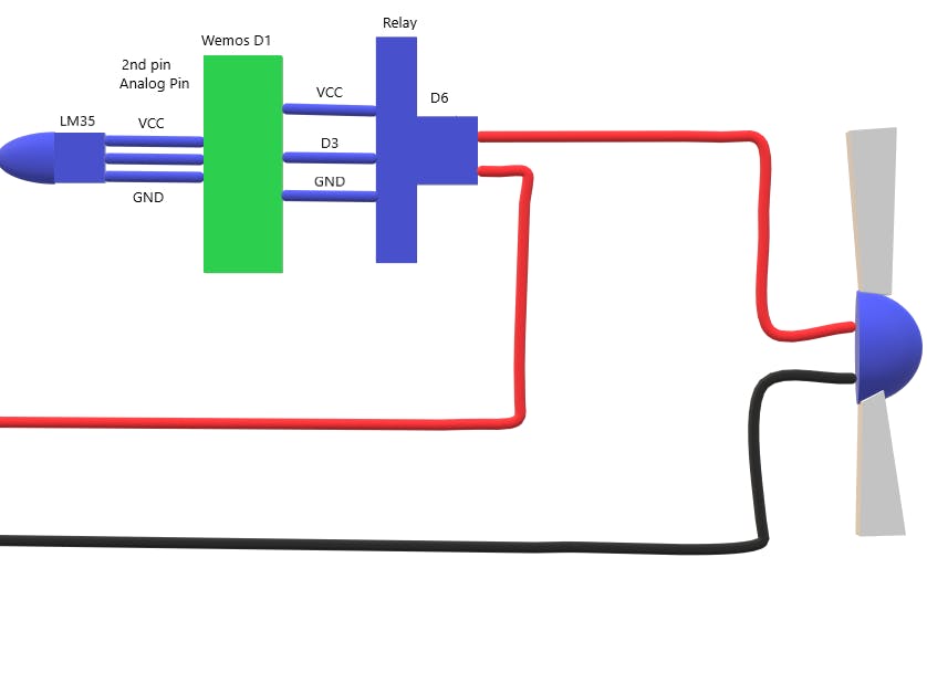
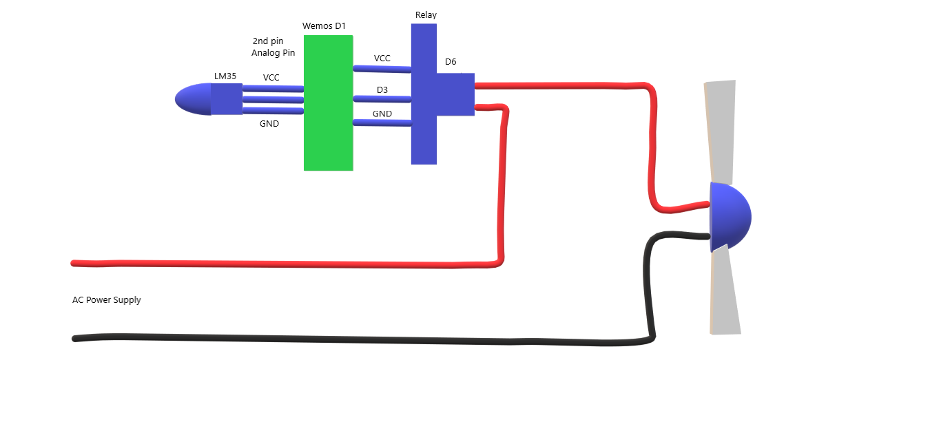
Using wemos d1, LM35 and 1-channel relay. we can control our room fan.
Youtube Link : https://youtu.be/5g3f60TlLw4
Wemos D1 :
- 11 digital input/output pins, all pins have interrupt/pwm/I2C/one-wire supported(except for D0)
- 1 analog input(3.2V max input)
- Micro USB connection
- Power jack, 9-24V power input.
- Compatible with Arduino
- Compatible with nodemcu
Microcontroller --> ESP-8266EX
Operating Voltage --> 3.3V
Digital I/O Pins --> 11
Analog Input Pins --> 1(Max input: 3.2V)
Clock Speed --> 80MHz/160MHz
Flash --> 4M bytes
Length --> 68.6mm
Width --> 53.4mm
Weight --> 25g
PinPin | Function | ESP-8266
TX | TXD | TXD
RX | RXD | RXD
A0 | Analog input, max 3.3V input | A0
D0 | IO | GPIO16
D1 | IO, SCL | GPIO5
D2 | IO, SDA | GPIO4
D3 | IO, 10k Pull-up | GPIO0
D4 | IO, 10k Pull-up, BUILTIN_LED | GPIO2
D5 | IO, SCK | GPIO14
D6 | IO, MISO | GPIO12
D7 | IO, MOSI | GPIO13
D8 | IO, 10k Pull-down, SS | GPIO15
G | Ground | GND
5V | 5V | -
3V3 | 3.3V | 3.3V
RST | Reset | RST
LM35 Sensor :
- Operating Voltage: 4-20V
- 3 pins: VCC, GND, SIGNAL
- SIGNAL pin changes voltage according to the temprature
LM35 is a 3 pin temperature sensor which requires a VCC and GND and in return the remaining third pin gives us an analog output. For its pin configurations refer to the Circuit Diagram below. This output is then provided to the ADCs present in AtMega 16 IC which according to a formula calculate the temperature in °C format.The LM35 series are precision integrated-circuit temperature sensors, whose output voltage is linearly proportional to the Celsius (Centigrade) temperature. The LM35 thus has an advantage over linear temperature sensors calibrated in ° Kelvin.
Relay :
This is a LOW Level 5V 2-channel relay interface board, and each channel needs a 15-20mA driver current. It can be used to control various appliances and equipment with large current. It is equiped with high-current relays that work under AC250V 10A or DC30V 10A. It has a standard interface that can be controlled directly by microcontroller.
Features- Relay Maximum output: DC 30V/10A, AC 250V/10A
- 2 Channel Relay Module with Optocoupler LOW Level Triger expansion board, which is compatible with arduino
- Standard interface that can be controlled directly by microcontroller ( 8051, AVR, *PIC, DSP, ARM, ARM, MSP430, TTL logic)
- Relay of high quality loose music relays SPDT. A common terminal, a normally open, one normally closed terminal
- optocoupler isolation, good anti-jamming
VCC : Connected to positive supply voltage (supply power according to relay voltage)
GND : Connected to negative supply voltage
IN1: Signal triggering terminal 1 of relay module
IN2: Signal triggering terminal 2 of relay module
Output:Each submodular of the relay has one NC(nomalclose), one NO(nomalopen) and one COM(Common). So there are 2 NC, 2 NO and 2 COM of the channel relay in total. NC stands for the normal close port contact and the state without power; No stands for the normal open port contact and the state with power. COM means the common port. You can choose NC port or NO port according to whether power or not.


Comments
Please log in or sign up to comment.