


Hardware components | ||||||
| × | 2 | ||||
| × | 1 | ||||
 |
| × | 1 | |||
 |
| × | 1 | |||
 |
| × | 1 | |||
Software apps and online services | ||||||
 |
| |||||
Hand tools and fabrication machines | ||||||
 |
| |||||
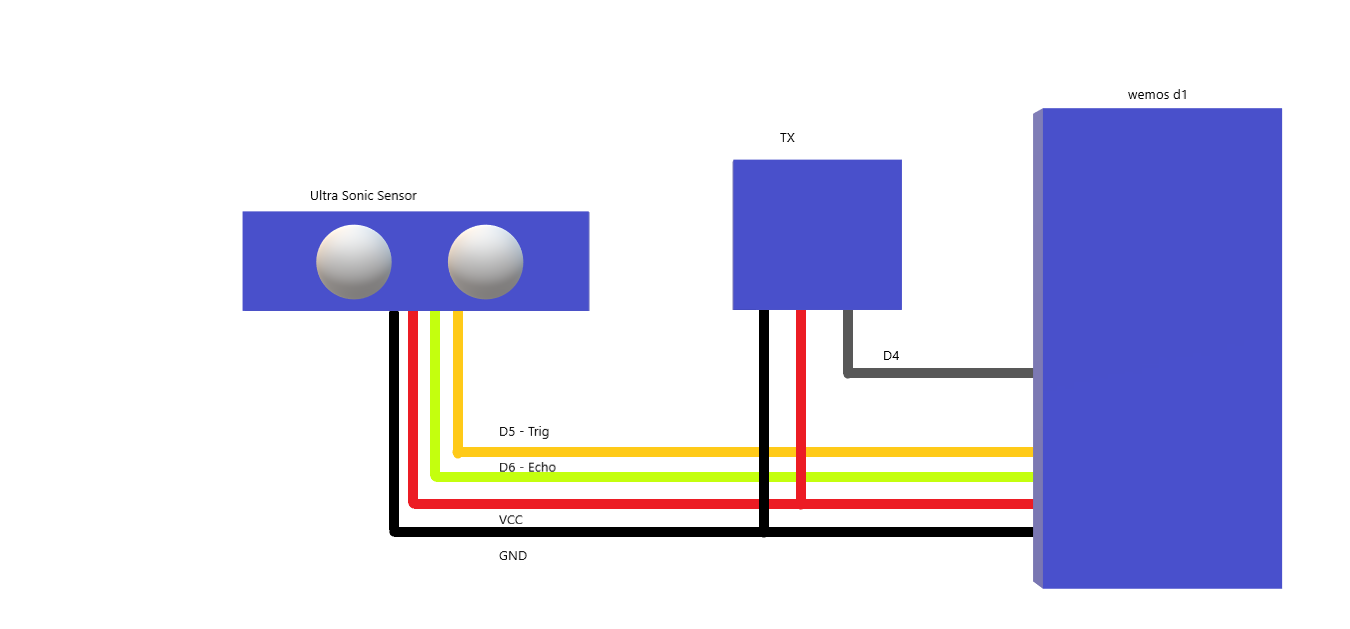
Using wemos d1 or arduino uno we can do this project.
Using radio frequency we are transmitting data that comes from ultrasonic and receiver receive that and display data on lcd.
1. Adraxx 433Mhz RSI Wireless Transmitter Receiver Module
The 433MHz RF link kit is consisted of transmitter and receiver, popularly used for remote control.
Features- Frequency: 433Mhz
- Modulation: ASK
- Receiver Data Output: High - 1/2 Vcc, Low - 0.7v
- Transmitor Input Voltage: 3-12V (high voltage = more transmitting power)
The popular link is like this: MCU -> Encoder -> Transmitter ------ Receiver -> Decoder -> MCU
PT2272(Encoder) and PT2262(Decoder) are optional, their existence is to
1) avoid confusing when multiple RF links in range
2) isolate disturbance.
You can integrate the encoding and decoding work to the MCUs on both side. Whenever there is no 433Mhz devices around, you may use it as direct cable connection.
2. Wemos D1- 11 digital input/output pins, all pins have interrupt/pwm/I2C/one-wire supported(except for D0)
- 1 analog input(3.2V max input)
- Micro USB connection
- Power jack, 9-24V power input.
- Compatible with Arduino
- Compatible with nodemcu
Microcontroller --> ESP-8266EX
Operating Voltage --> 3.3V
Digital I/O Pins --> 11
Analog Input Pins --> 1(Max input: 3.2V)
Clock Speed --> 80MHz/160MHz
Flash --> 4M bytes
Length --> 68.6mm
Width --> 53.4mm
Weight --> 25g
PinsPin | Function | ESP-8266
TX | TXD | TXD
RX | RXD | RXD
A0 | Analog input, max 3.3V input | A0
D0 | IO | GPIO16
D1 | IO, SCL | GPIO5
D2 | IO, SDA | GPIO4
D3 | IO, 10k Pull-up | GPIO0
D4 | IO, 10k Pull-up, BUILTIN_LED | GPIO2
D5 | IO, SCK | GPIO14
D6 | IO, MISO | GPIO12
D7 | IO, MOSI | GPIO13
D8 | IO, 10k Pull-down, SS | GPIO15
G | Ground | GND
5V | 5V | -
3V3 | 3.3V | 3.3V
RST | Reset | RST
3. UltraSonic Sensor :
If you are sourcing a ultrasonic ranging module, the HC-SR04 is good choose. Its stable performance and high ranging accuracy make it a popular module in electronic market.Compared to the Shap IR ranging module, HC-SR04 is more inexpensive than it. But it has the same ranging accuracy and longer ranging distance.
Specifications- Power supply: 5V DC
- Quiescent current: <2mA
- Effectual angle: <15°
- Ranging distance: 2cm – 500 cm
- Resolution: 1 cm
- Ultrasonic Frequency: 40k Hz
A short ultrasonic pulse is transmitted at the time 0, reflected by an object. The senor receives this signal and converts it to an electric signal. The next pulse can be transmitted when the echo is faded away. This time period is called cycle period. The recommend cycle period should be no less than 50ms. If a 10μs width trigger pulse is sent to the signal pin, the Ultrasonic module will output eight 40kHz ultrasonic signal and detect the echo back. The measured distance is proportional to the echo pulse width and can be calculated by the formula above. If no obstacle is detected, the output pin will give a 38ms high level signal.
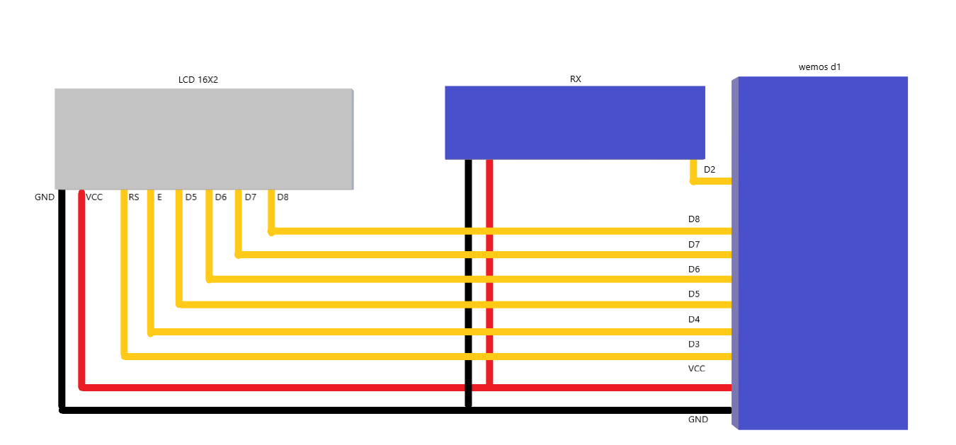
4. LCD 16X2 :
LCD (Liquid Crystal Display) screen is an electronic display module and find a wide range of applications. A 16x2 LCD display is very basic module and is very commonly used in various devices and circuits. These modules are preferred over seven segments and other multi segment LEDs. The reasons being: LCDs are economical; easily programmable; have no limitation of displaying special & even custom characters (unlike in seven segments), animations and so on.
A 16x2 LCD means it can display 16 characters per line and there are 2 such lines. In this LCD each character is displayed in 5x7 pixel matrix. This LCD has two registers, namely, Command and Data.
The command register stores the command instructions given to the LCD. A command is an instruction given to LCD to do a predefined task like initializing it, clearing its screen, setting the cursor position, controlling display etc. The data register stores the data to be displayed on the LCD. The data is the ASCII value of the character to be displayed on the LCD. Click to learn more about internal structure of a LCD.
Pin No || Function || Name
1 || Ground (0V) || Ground
2 || Supply voltage; 5V (4.7V – 5.3V) || Vcc
3 || Contrast adjustment; through a variable resistor || VEE
4 || Selects command register when low; and data register when high || Register Select
5 || Low to write to the register; High to read from the register || Read/write
6 || Sends data to data pins when a high to low pulse is given || Enable
7 - 14 || 8-bit data pins || DB0 DB1 DB2 DB3 DB4 DB5 DB6 DB7
15 || Backlight VCC (5V) || Led+
16 || Backlight Ground (0V) || Led-


Comments
Please log in or sign up to comment.