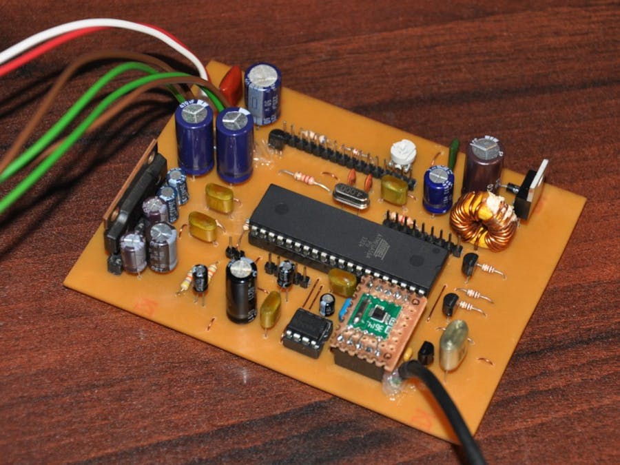
This tuner circuit is a quick prototype which I built to test the RDA5807M FM radio tuner IC. RDA5807M is a single-chip tuner IC with RDS and MPX decoder, and it equipped with I2C interface for control. The main reason to build this prototype is to understand the behavior of this chip.
At the time of this design, the website of the RDA microelectronics is not accessible from my location. Because of this reason, I download different versions of RDA5807M datasheets from the internet. While going-through those datasheets, I observed that it comes with limited information. Finally, I decided to build this receiver to verify some of those parameters and to review the RDS functionality of the chip.
I built this receiver around ATmega16A MCU. I choose this MCU because I got a few of ATmega16A MCUs in my inventory and also due to the higher number of I/O pin count.
In this design, the volume is controlled using M62429 IC. For the output stage, I used AN7147N, 2×5.3W audio power amplifier IC.
Based on the specifications of the switching-regulator and power amplifier, this circuit can drive between 9V to 20V DC input. At prototyping stages, we power this circuit using a 12V - 2.5A power supply unit.
The main problem which I encounter with this project is its PCB design. At prototyping stages, I did a couple of PCB designs to avoid interference and distortions. It seems like RDA5807M and AN7147N are sensitive to noise and need a proper PCB layout. In this final design, I got excellent results, and it performs better than I expected.
The firmware of this receiver is developed using two verification buffers to avoid RDS decode errors. This technique helps to filter garbage data received due to poor reception.
The current version of the firmware supports both manual and auto-tuning functionalities with 100kHz spacing and, it is set to operate within 87MHz to 108MHz range.
The circuit diagram, PCB designs and firmware source code of this receiver are available on GitHub.


Comments
Please log in or sign up to comment.