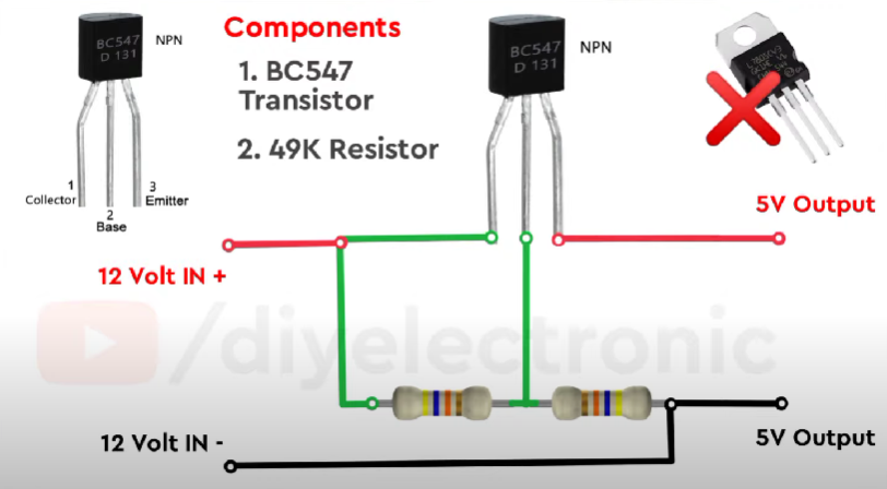
In this project, we are going to create a step-down voltage regulator using a BC547 transistor and a resistor voltage divider circuit. The voltage regulator will be able to lower the voltage from a higher input voltage to a stable, lower output voltage.
The BC547 transistor will be used in a common emitter configuration, which means that the input voltage will be applied to the base of the transistor, and the output voltage will be taken from the collector. The resistor voltage divider circuit will be connected between the input voltage and the base of the transistor to provide a lower voltage input to the transistor.
By using the some basic components I am going to make 7805 Voltage Regulator we need for making this circuit.- BC547 Transistor
- 47K Resistor
Before continue this article. Make your next project a reality with JLCPCB!The premier PCB company in China, delivering top-notch 1-8 Layer PCBs starting at only $2 and PCBA at an unbeatable $0 (with free setup and stencil included). Register now using my link and receive a juicy $54 new user coupon code to electrify your creativity! Link : https://jlcpcb.com/IUP
To build this circuit, I am providing you a schematic diagram:This DIY voltage regulator can be used in a variety of electronic projects where a stable, lower voltage is required, such as powering microcontrollers, sensors, or other low-power devices. It is a simple and cost-effective solution that can be easily built using common electronic components.
By the way you can also watch the making video:


Comments
Please log in or sign up to comment.