Hii friends welcome in “DiY Projects Lab” In this post i”ll show you how to easily we can program our ESP8266 NodeMCU with Arduino IDE I will upload a simple sketch of LED blinking to ESP8266 board.
1st we learn
What is an ESP8266?
ESP8266 ESP-01 WiFi Module
The ESP8266 is a Wi-Fi capable Chip (SoC) with a full TCP / IP stack and a microcontroller, manufactured by Espressif system , a Chinese company. The first chip became known to the market with the ESP-01 module, developed by the company AI-Thinker. This small module allows other microcontrollers so you can use it to connect to your Wi-Fi wireless network and make simple TCP / IP connections using Hayes-style commands (AT commands). connect nodemcu to the Internet, web server with real web pages, let your smartphone connect to it.
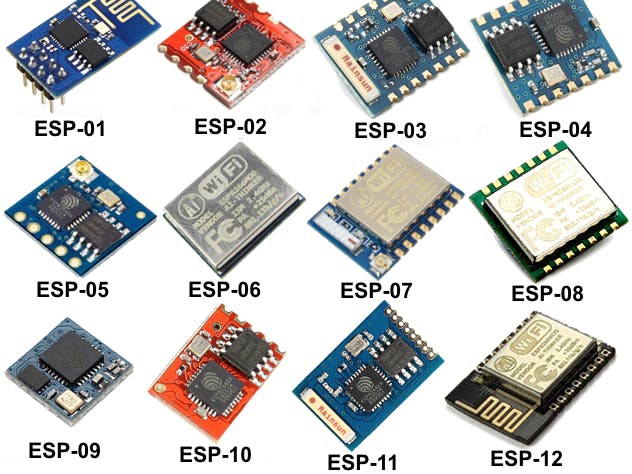
ESP8266 modulesLet’s start with ESP ModuleThese are programmable microcontroller type boards, with a chipset from the company Espressif Systems, in the Arduino style, which can also run both compiled and interpreted Python style languages.
Small sizeLow consumptionLarge range of sizes and computational speedInclude WiFi baseLarge variety of memory space available for our code.Low cost
Cons:Are susceptible to electromagnetic noiseHas a limited number of analog outputs
Characteristics• 32-bit RISC CPU: Tensilica Xtensa LX106 clocked at 80 MHz. CPU and flash memory clock can be doubled by overclocking on some devices. The CPU can run at 160 MHz and the flash memory can run between 40 MHz and 80 MHz. It varies depending on the version of the chip.• 64 KB program RAM, 96 KB data RAM• External QSPI flash memory capacity from 512 KB to 4 MB (can handle up to 16 MB)o Integrated: TR switch, balun, LNA, RF power amplifier and an impedance matching networko WEP and WPA / WPA2 authentication support• 16-pin GPIO (General Purpose Inputs / Outputs)• SPI, I²C,• I²S interface with DMA (shared pins with GPIO)• Dedicated UART pins, plus one UART for transmission only that can be enabled through the GPIO2 pin• 1 10-bit ADC converter
Adding ESP8266 Board in arduino IDEFirst we need to download Arduino IDE program to upload code to if you already installed it in your computer you can move ahead.or you can download it from Arduino IDE DOWNLOAD.
after install the IDE on you PC and open the IDE, now go to FILE > PREFERENCES
To do this, we must open the File menu, and then Preferences.
We will see this panel, at the bottom the text box labeled Additional Card URLs Manager. Inside it, using copy and paste, you must enter the text indicated here:
http://arduino.esp8266.com/stable/package_esp8266com_index.json
(copy and paste in the box):
Then click on the Ok button.
Now we must go to the Tools menu, then select board
Now search “ESP8266” and click on “Install” and install board to arduino IDE
When we open Tools again, and then Plate, we slide the list to see what appears at the end of it (below), and we see that the options referring to the ESP8266 already exist:
Program example:
In this example we will work on two board models that use the ESP8266 chip: ESP-01 and NodeMCU (ESP-12E).
The NodeMCU is a development board that contains the built -in ESP-12E module, plus all the necessary support elements to communicate with it, including a USB connector, voltage regulator, reset button, a “flash” button that is used to program the module, rows of plug-in pins, etc.
We will design a simple circuit to blink an LED on ESPs using the Arduino IDE to program them.
The question one can ask is why is it always the first thing that is taught to make an LED blink?The answer is that if we can make an LED blink using a device’s output pin, it means that we can turn any electronic device on or off.About GPIOs, the following table is a quick reference on how to map ESP8266 GPIOs in Arduino code.
Here is the location of each pin on the physical board:
ESP01NodeMCU / ESP-12E
Important: in the next section, called “How to write the program in the Arduino IDE”, when we define: output = 0 we refer to GPIO 0, and if we define: output = 2 we refer to GPIO 2. In the internal signature of ESP it is defined like this. No need to worry about this, just remember that 0 refers to GPIO 0 and 2 refers to GPIO 2.
NextPCB PCB Manufacturers CompanyNEXTPCB PCB
Thanks so much NextPCB for sponsor this project. Nextpcb offer For New Customer, Your First Order Will Be 10 PCBs for just $0 at Free.
NextPCB one of the world's most professional PCB manufacturers based in China. With professional PCB manufacturing capabilities, for each file of our customer will be double-checked by more than 14 years PCB engineers. they handle the whole process of PCBs including the PCB assembly, PCB manufacturing, testing and final shipment.
GET $100 Coupan For 1st Order :- Sign up on Nextpcb
How to write the program in the Arduino IDEThe program to blink an LED is very simple:
int LED = 5; // Assign LED pin i.e: D1 on NodeMCU
void setup() {
// initialize GPIO 5 as an output
pinMode(LED, OUTPUT);
}
void loop() {
digitalWrite(LED, HIGH); // turn the LED on
delay(1000); // wait for a second
digitalWrite(LED, LOW); // turn the LED off
delay(1000); // wait for a second
}To upload code to an ESP-01, a USB communication must be established through a USB converter at TTL levels (that handles 3.3V voltages) to the TX / RX serial connection of the ESP8266, with a module like the one shown see in the figure. There are many models, but it is advisable to look for one that has an FTDI chip and that on its board facilitates the conversion of voltages from 5V to 3.3V (which is the voltage with which the ESP8266 works ).
It is important to note that the first thing we must do, when buying it, and before connecting them, is to look for the voltage selector from 5V to 3.3V. We must make sure that the FTDI module is set to 3.3V mode of operation, as the image below shows.
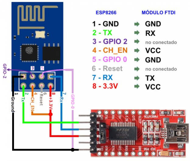
The circuit below indicates the connections that we must make to establish communication from the ESP-01, through the FTDI module, to the USB connector, to achieve serial communication.
The connections are:
• RX ► TX
• TX ► RX
• CH_PD ► 3.3V
• GPIO 0 ► GND
• VCC ► 3.3V
• GND ► GND
Note: In the circuit in the picture above, GPIO 0 is connected to GND. This is because we want to upload code. When uploading a program for the first time from the Arduino IDE, the ESP is required to write a new firmware to its flash – firmware is a low-level, internal software that allows controlling electrical circuits. In normal use (when we are not writing new firmware to flash memory) the GPIO pin 0 connects to VCC ( 3.3V ).
The final run: Circuit for the ESP-01 and the LED
After uploading the code to the module, disconnect from the computer and rewire following the diagram below:
By connecting the 3.3V power supply to the ESP-01, everything will be ready. If things went well, the LED should blink on and off every 1 second.
visit my website [LINK} For More tutorial


Comments
Please log in or sign up to comment.