


Surely every amateur radio operator, and even just an ordinary person, has seen the projects of electronic LED hearts. There are usually 2 varieties of them:
1) The simplest ones are made according to the type of multivibrator on transistors or timers of the 555 series. They are not expensive, the effects are also frankly so-so :) but they are suitable for beginners to build.
2) The software is more complicated-made on microcontrollers. In this version, of course, the total cost of the project is more expensive, but there are also much more opportunities. You can write various beautiful effects, and not just switching one group of LEDs to another and back as in the first option.
But, both the first and second options are developed, as a rule, as a gift to a loved one or a beloved for Valentine's day on February 14. Surely, in most cases, such a gift will be included for a short time directly on the holiday itself and for some time after the holiday itself. And here's what I thought, what if we make a heart-shaped watch in the form of silk-screen printing, and additionally put another heart in them, but this time smaller on red LEDs. Said - done! What happened is for you to judge.
Such an electronic project is perfect not only as a gift for Valentine's day, but also useful in everyday life. The device shows the current time and temperature sequentially, well, how can it be without animation of the heart, for example, every second it can smoothly light up and gradually go out, but this is only one of the options, you can make it glow constantly, and you can choose other options about this below.
The animation of the LED heart will always remind your significant other about you and give pleasant emotions everywhere, whether at home or in the office.
I developed the printed circuit board as usual in the Altium Designer 15 program, I am completely satisfied with it. The printed circuit board turned out to be 2-layer without any problems. Dimensions 90 x 85 mm. It is soldered easily, radio elements are relatively large, for example, all SMD 0805, LEDs are large 5 mm, integrated circuits are all in soldered cases, there are no BGA and other things here. I ordered the production of the printed circuit board in PCBWay.
Link to this project on PCBWay for ordering a pcb
With the installed components, it looks like this:
By the way, the socket for the battery was soldered from the motherboard from the PC just slightly bent the conclusions. There is no way to spend extra money on Ali Express, but it's also a so-so idea to make the conclusions stick through, it doesn't look very nice from the front, so I did it like this.
Functions:- - Display of the current time.
- - Temperature display.
- - Temperature measurement range: -55...+125 gr. S.
- - Measurement accuracy: ±0.5 gr. S. in the range of -10...+85 gr. S.
- - Display discreteness: 0.1 gr. S.
- - Alternate mode of displaying information. Customizable.
- - Night mode. Customizable.
- - Reducing the brightness of the display in the night mode at the set time, with the possibility of completely disabling the display and the heart.
- - 7 levels of display brightness in daytime mode.
- - The effects for the heart are divided into 2 groups. They are being configured.
- Group 1 - effects shown every second.
- Group 2 - effects shown in the interval from 1... 60 minutes
- - Menu. Control of the 4th buttons. «MENU», «UP», «DOWN», «ENTER».
- - Saving settings in non-volatile EEPROM memory.
- - The ability to reset to the default settings.
Short video:
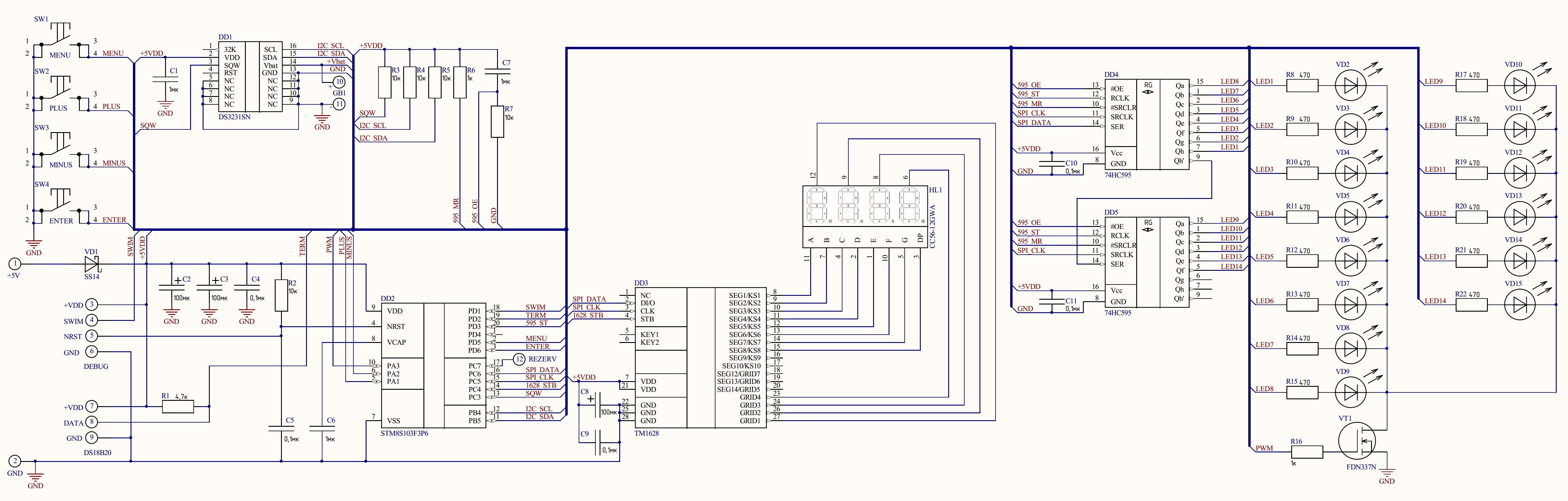
Description of the hardware and softwareThe clock is made on an 8-bit STM8S103F3P6 microcontroller in the TSSOP-20 case. A 7-segment 4-bit display with a common cathode shows the information. The display is controlled by a specialized microchip of the company Titan Microelectronics TM1628. It communicates with the microcontroller via the hardware SPI interface. Data is sent from the PC6 port, clock pulses are sent from the PC5, and strobing pulses are sent from the PC4. All the work on the output of data to the display is taken by this chip, that is, you do not need to use interrupts to provide a dynamic indication. Just when necessary, we send data to the led driver and do other things.
The DS3231 chip in the SOP-16 case is used as a real-time clock (RTC). This chip has a "magic" output called SQW, which generates a positive polarity pulse every second.
This MC has a PC3 (TLI) port-Top Level Interrupt (the highest priority for processing interrupts) just the same, the SQW signal is wound up on this port. That is, as soon as the pulse from the RTC came, it says STM8 Hey, bro? throw everything away, a whole second has already passed:), let's quickly go to the interrupt handler and set the flag! In the handler of this interrupt, a special flag is set to 1, I called it Flag1Sec, and in the main cycle of the program, this very flag is checked and when it is in 1, data is read from the RTC and when it is necessary, it will be shown on the display and immediately after that the flag will be reset to 0. After that, the microcontroller will constantly check whether the flag has been set after 1 second of time in the interrupt handler and the whole process will be repeated indefinitely, that is, while the clock is turned on. Why complicate something? Only everything you need IMHO.
The heart is implemented on 14-and red 5mm slightly matte LEDs :) I got them at my last job, borrowed them from unnecessary front panels from old computers. They regularly showed HDD activity there naturally. I recommend you to use matte, too super-bright may dazzle - but this is not accurate :)), the brightness is generally adjusted from 1... 100%. So it was a retreat. We continue.
They control the LEDs of 2-a shift 8-bit serial registers 74HC595 working all according to the same hardware SPI. The hardware PWM on timer 2 helps the heart with the brightness control signal, namely channel 3, the output of which goes to port PA3 is the 10th pin of the microcontroller. The key for the LEDs on the N-channel field-effect transistor VT1 - FDN337N.
The MC is clocked from the built-in HSI generator at 16 MHz, program delays are implemented on the TIM4 timer without the use of interrupts. The program is written in C in the ST Visual Develop v4 development environment.3.12 & the Cosmic compiler. I tried as much as possible to write directly to registers without using any libraries.
The data is displayed on the display in alternating mode. For example, 10 seconds. the time is shown, then 3 seconds. temperature well, all over again. How long to show only you decide. It is configured in a special simple MENU, in it you can also enable/disable effects for the heart, as well as configure other options.
The temperature sensor is connected to the PD2 port. As a temperature sensor, the well-known folk digital DS18B20 is used, which operates over the 1WIRE bus. For the reliability of the readings, it must be placed outside the watch case. When testing, I soldered it immediately to the board and O My God:)) I noticed that the longer the clock works, the greater the temperature increase by an average of 1-2 degrees Celsius. To the printed circuit board, the wiring from it is soldered to the contact pads on the back of the board. I did not make any connectors, if you want, you can place any connector on the case of the watch itself and solder to the board, in principle, no problems.
4 buttons are mainly used to adjust the options in the menu, you need to choose their height based on the size of your body to look nice. You can buy buttons of different heights, for example, on Ali Express, now this is not a problem.
The Schottky diode VD1 as a protection against reverse polarity.
The entire structure is powered by a stabilized +5V source with a load current of at least 500mA (depends on the set brightness). A programmer is connected to the contact pads on the back of the board to fill the firmware via the SWIM interface, all contacts are signed which wire to solder where will not be a problem.
An important point to mention is the minimum brightness of the display at night. The fact is that the brightness at night is forced to be at the very minimum and it can not be made less, but it seems like it is asking for more :)
Therefore, I advise everyone who will repeat this project. Consider the option of slightly toning the display with a tinting film, which one I can't say, you need to try different options. Again, everything is purely individual, you need to select / test. But, this is all relevant when the display lights up dimly, if you select the option in the MENU to completely turn off the display, then you can not bother with this.
Unfortunately, the MENU description does not fit completely here, but this is not a problem, you can get acquainted with this by visiting my website or instagram.
The articles are in Russian, so please use Google Translator.
Downloading the program:Attention! Carefully connect the programming wires, in case of an error, the device may fail! You need to download the firmware using the STVP-ST Visual Programmer program. Immediately after downloading the firmware, go to the "OPTION BYTE" tab, you need to configure AFR3 as an alternative function, select Port C3 Alternate Function = TLI from the drop-down list. This is very important, nothing will work without this option! After you have selected it, click on the red arrow icon with the chip at the top and upload it to the microcontroller. Disconnect the programmer from the board. After downloading the romantic clock-thermometer software, you are ready to work with the default settings.


Comments
Please log in or sign up to comment.