


Hardware components | ||||||
 |
| × | 1 | |||
 |
| × | 1 | |||
| × | 1 | ||||
This project was created for the Winter 2022-23 ECE434 course at Rose-Hulman Institute of Technology, taught by Dr Yoder. I wanted to do a project that integrated a microphone and produced a display of the frequency spectrum.
I began this project by finding a suitable display, first attempting to work with a 64x32 LED matrix display from adafruit, but the Beaglebone black currently does not have any code to support working with that part and I could not get it working. Instead, I used an 8x8 bicolor LED matrix also from Adafruit, as it could accomplish most of the same output albeit at a much smaller resolution.
I also found a suitable microphone in the MAX9418 from Adafruit, though I also ordered a MAX4466 to be safe. As it turns out, both will work though they may require some additional resistors to reduce the amplitude below the beaglebone's 1.8v maximum. I used a 1.5V to the input, then a 1.8V to ground.
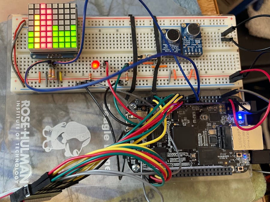
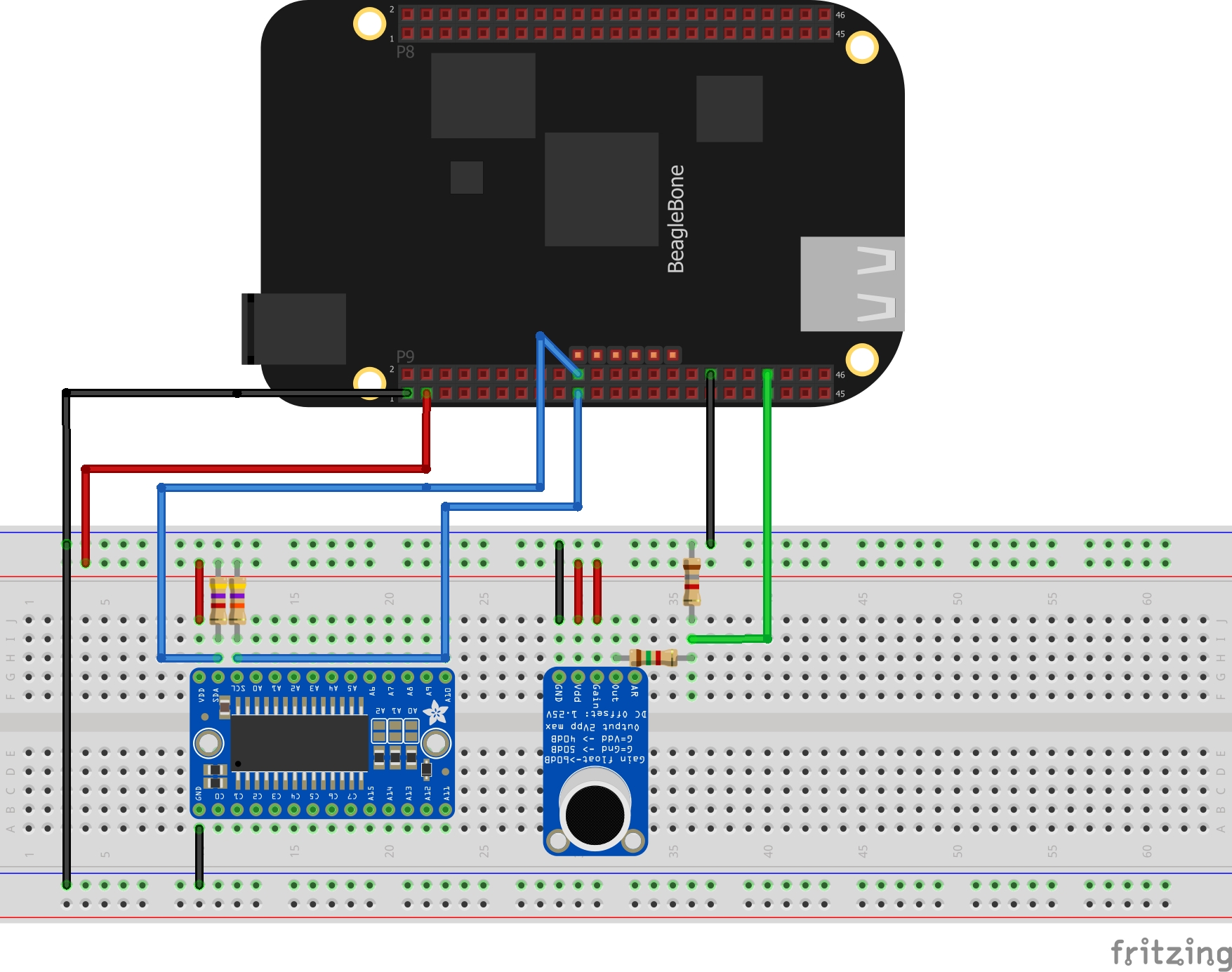
To wire this up, follow the diagram below. The larger chip on the left is the backpack that the LED matrix sits on.
To run the program, simply clone the github library linked below, follow the install directions, start the program and play some music near the microphone. The LED matrix should display a frequency spectrum, as pictured in the thumbnail.
The theory of operation is as follows:
Audio input is generated via the industrial io system on the beaglebone black, sampled at 96kHz to create an audio signal. I then used numpy to make a 481-point FFT of this input, creating 481 different magnitudes at different frequencies. I then split that FFT into a number of buckets according to the display width. The relative magnitude of the highest sample in each bucket to the minimum and maximum determines the height of its output, and that height relative to the display maximum height determines its color. A series of if-else statements produce a matrix to output to the display, with all of the code functions fully modular and variable to different displays so long as the format is compatible.
The code is set up to output an array with hex values for each column, one bit for each LED in the column and two hex values per column. The first hex value is green and the second is red, combining to make yellow between 50 and 75% of the maximum volume. The integration would need to send this array to the display to be output in the correct order. It assumes the 0, 0 is in the bottom right of the display so that may be a desired change for a future user. As well, the setup of the display would need to be updated if the array size would be different as the initial array is hard coded and it only gets modified as the code runs.
For more info, check out the github linked below or the elinux.org project page https://elinux.org/ECE434_Project_-_Audio_Spectrum_Display.

Comments
Please log in or sign up to comment.