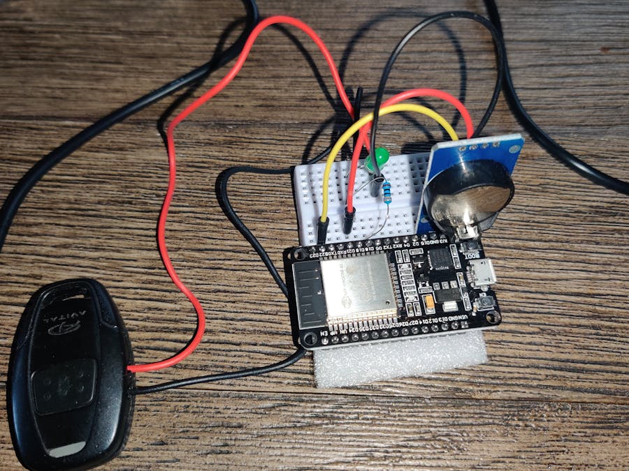
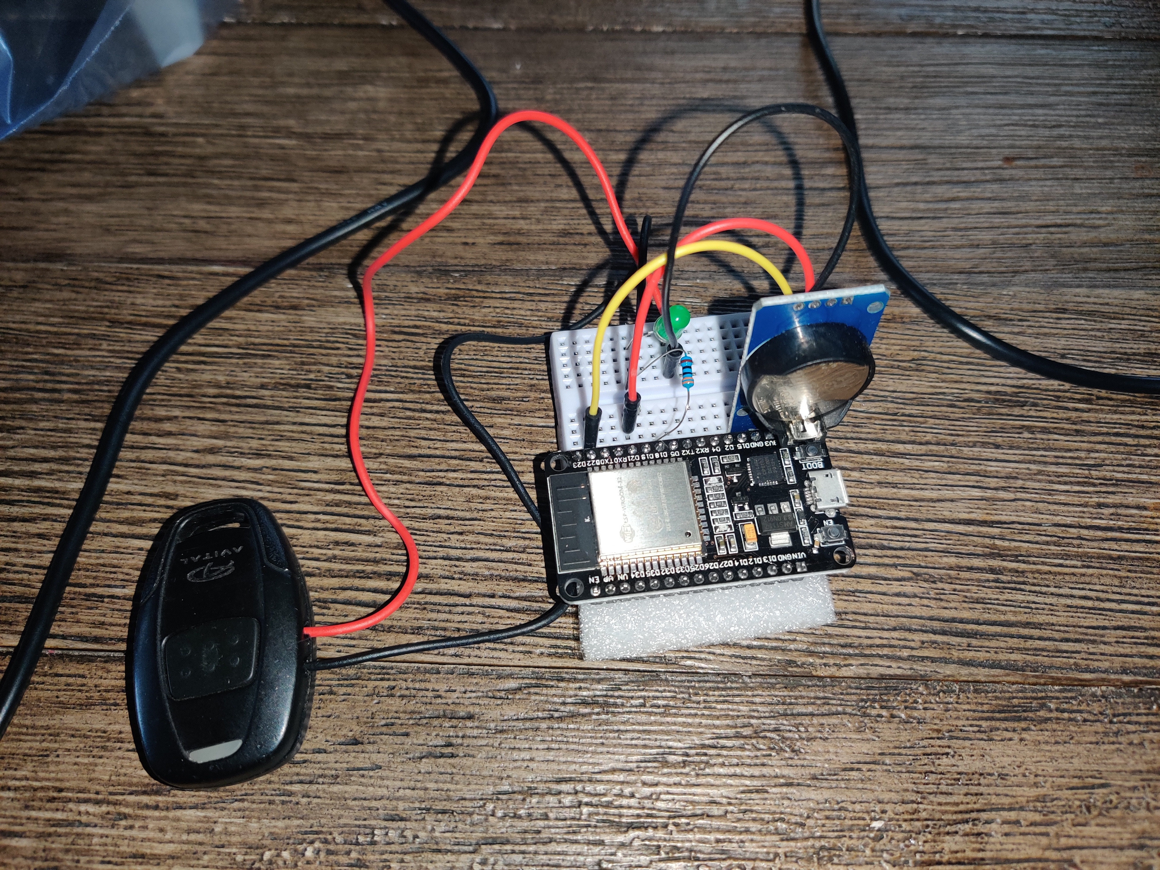
I have remote start on my vehicle that on its own works as it should. My problem is I sleep in until I have to rush out the door for work. Not giving the car time to warm up even if I remote start it the second I open my eyes.
Bringing me to this project. To have a microcontroller use the fob from remote start and automatically "pressing the fob"( not literally) for me at multiple set times of the day, day of the week. Also with function to start from phone and unlock doors.
At first I used arduino uno, then nano power savings, then wanted wifi abilities to bring me to esp32. I used RTC to keep time for the alarms.
1st step. How to have microcontroller command remote start.
Options 1. Use relay module and Fob.
Solder wires on each side of Fob button contacts. Microcontroller to trigger relay, in term shorting button as if it were pressed.
Problems is relay module uses power and is another module needed. I only had 4 bank relay on hand.
Option 2. digitalWrite straight to Fob.
In order to do this you'll have to figure out some things about your Fob.
- Voltage it runs on.
- Does all that voltage go through button or is it dropped down.
- Is button positive triggered or negative.
For my case my Fob runs on 3volt cell battery. The button is positive and has full voltage. My microcontroller running on 5V.
I used a multimeter to test for DC Volts between one side of button contact and other to battery negative.
If I had 3V voltage then that tells me the contact I was on is the power side and is positive.
If no voltage then I would press the button while checking. Meaning this is the trigger side of button. This is the side you inject voltage to trigger Fob button.
Still No, voltage then I'll check between contacts of button to the Positive of battery. No power, press button. ?
If voltage. The button is triggered from the negative side. To be honest I'm not sure what you can do here besides using relay module.
Okay, I got my trigger side of button. Call it A
I solder wire to A and connected to analog port
A separate wire to negative contact of battery holder. Going to ground on controller. Because You have to have common ground/negative In order to inject volts from controller to fob. A complete circuit.
Now my controller setup is 5 volts because that's what I had. When I digitalWrite it's going to output 5 volts into the fob. Not knowing what would happen and wanted to find out if the fob could handle the extra voltage. I SENT IT.
Hey, It Works just fine. 2 Weeks and Fob is doing just fine. Cell battery is fine. I could have used the voltage port of arduino and solder to the Positive battery holder and eliminated the cell battery but figured I better not over volt it full time. In case the fob in fact is not compatible with 5v and with short pulses of 5v it can disperse the heat quick enough. My not so expert opinion I think the fob is compatible with 5v and maybe even boost the antenna signal but let's not go looking for problems if it works with cell battery just as well.
Option 3. Some remote starters have a 3 pulse Lock input trigger wire. Such as Excalibur AL-xx70-B
I haven't tested. Theoretically you would need relay module as the vehicle.
The trigger wire on remote start above is - negative trigger. Meaning if its ground out 3 times it'll trigger the start. So relay module between this wire and ground on vehicle. Then control relay module as needed.
If you wanted to unlock doors, another relay to door lock trigger wire and other side to its respective polarity. Some vehicles are negative. Some are positive.
Now the code.
The small sketch is for the Nano and other compatible boards. It's basic and has no wifi. Hard code your alarm times.
Bigger Sketch is for the esp32 and has wifi.
Connect to esp32 SSID: Remotestart5 Password: qabnph4gsffu
Change alarm times from 192.164.4.1 web interface. Submit 1 at a time in military time, don't add 0 in front of single number time. Say 5:07 P.M Hour set to 17 Min. set to 7
I'm a beginner. I've only made it to 26 out of 63 arduino video lessons with Paul McWhorter.
I know enough that I was able to use others examples and piece together this.
The code is crude and I'm sure needs simplified and expert to take out overlapping codes and nonsense.
Libraries for ESP32
https://randomnerdtutorials.com/esp32-esp8266-input-data-html-form/ HTML
https://github.com/rodan/ds3231 RTC
Others you get when setting up ESP32 to arduino IDE
Libraries for Arduino uno, nano.With power savings. Basic code. preset hard coded alarm times. No wifi.
https://github.com/rocketscream/Low-Power
Hook up Fob wires to microcontroller. for me Pinout 19 on esp32, ground.1
pin 18 on nano and ground
RTC scl, sca, 5v, grnd


Comments
Please log in or sign up to comment.