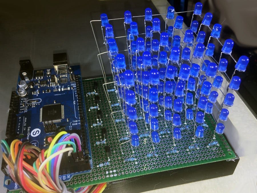
Most people love LED cubes, but big ones, like 8x8x8, are a lot of work both to build and to program. Small ones (3x3x3 or 4x4x4) are easy to build, both because they don't require large numbers of LEDs, but also because they don't require external hardware like shift registers and high-side drivers to manage the cube. But they really aren't the same as a big cube.
My objective from the start of this project was to create an easy to build cube and then create enough cool software to make it possible to enjoy the feel of a big cube without all the drudgery required to build a big one. So this is a 5x5x5 cube that can be powered directly by an Arduino Mega without shift registers of any auxiliary hardware other than 5 transistors (used to pull a whole layer - the cathodes of 25 LED's, to ground). Why do I want to avoid shift registers? Because they are absolutely horrible to hand wire. (I've tried it.) You really need to design and fabricate a PC board if you want to use them.
I have written a whole lot of code for big cubes in the past, so I have adapted a bunch of existing cube animations to run on this 5x5x5 cube.
This is actually the first of three projects like this. The 2nd one is here. It is a 5x5x5 RGB cube, very similar in design to this cube, but a harder to build. The third is here - a 8x8x8 single color cube, again with minimum external hardware.
NOTE: Before I go any further here, I'm not the first to suggest a 5x5x5 cube powered with a MEGA. MEGA DAS published a similar project here in 2017. The hardware in both projects is almost identical. I hadn't seen the earlier one until I started this writeup, so my pinouts are different, and the resistor values are different, but otherwise,the hardware is almost identical. I am publishing this mostly because I have a lot of experience writing cube software. I'm hoping my software will convince a few people to build a cube who might not otherwise!
The video above is a sine wave function where amplitude is on the z axis and time is represented as horizontal distance from the center of the cube. It's an awesome classic on a big cube, but not too bad on this 5x5x5!
I am including two other videos. Both are of the same thing - 14 animations for the 5x5x5 cube. I'm not sure which is better, so I've included both. And in case it is not obvious, cubes look much cooler in person than they do in video!
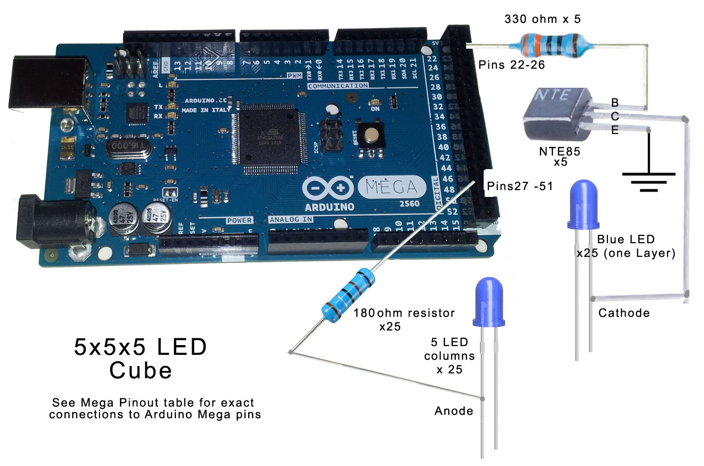
HARDWAREThe Mega has lots of digital IO pins. We use 5 for pulling the cathodes for each layer low, and 25 more to drive the anodes high for each of the 25 LEDs within a layer. Using this approach, the Mega actually has enough IO pins to build a 6x6x6 cube. But the other consideration, if we are trying to keep this simple is power. The Mega's current limits are 40 ma per pin, and 200 ma total on all pins. Blue LEDs have a forward drop of about 3 volts, our common cathode transistors drop another 0.7 volts. So with a 5 volt supply and a 180 ohm resistor, each LED will draw 7.2 ma. 25 LEDs/layer draws 180ma if all are on at once. We only turn one layer on at a time, so we meet all the Mega's current limitations, as long as we use NPN transistors to pull all the cathodes in a layer to ground. The base current to one of those transistors adds another 5 ma to the total load on the Mega, but we keep the total below 200 ma. at about 185 ma. So, for all the reasons above, I chose 180 ohm resistors to pair with our LEDs.
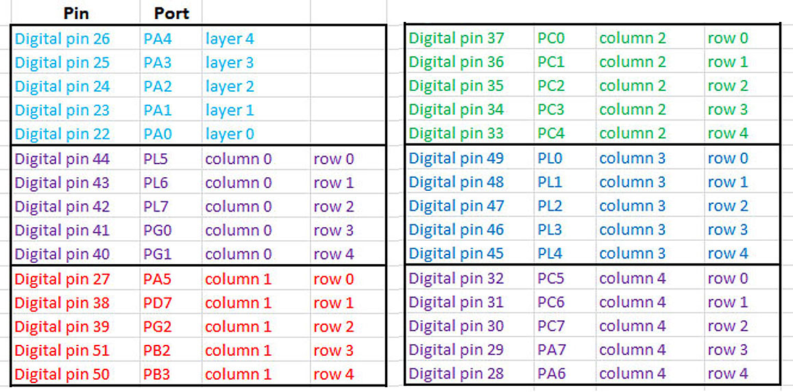
The chart above shows the how Mega's digital pins connect to the cube. Pins 22 - 26 are the 5 pins that drive the transistors that connect the LED's cathodes to ground. Pins 27-51 go through the 180 ohm resistors to the anodes of 25 LEDs in a layer.
You may be wondering why this pinout arrangement looks slightly confusing. My software uses direct port access rather than digitalWrites to configure the anodes, that is, to set each of the 25 LEDs in a layer either on or off. This saves a lot of time and means that the LEDs are on longer than they would be if you spent a lot of time doing digitalWrites. So the pinouts are arranged in a way to help organize references to these digital ports rather than the actual pin numbers. More on all that that when we get to software.
CUBE CONSTRUCTIONThere are a lot of opinions about how to built a cube, regardless of its size. The task is tedious no matter what your approach. And you have to exercise both care and patience to get a good result. I will show you how I built this one, but there are other instructions online if you prefer.
Construction of this cube begins with lead forming and soldering LEDs together in columns of 5. Then panels are formed by soldering together 5 columns, and finally the cube is formed by soldering together 5 panels. People who have never built a cube before don't realize how difficult it is to build a perfect cube. Small errors in lead angles quickly accumulate and even small differences in spacing are easily visible. So the lead forming step is critical. If you take your time and do it right, you won't get a perfect cube, but you will get a reasonable looking one.
The anodes are the longer lead of the LED and they go down, but they need to be bent out to the side of the LED so that vertical rows of LEDs' anodes can be soldered together. The anode offset and the cathode lead must be a 90 degrees to each other, as shown in these photos.
I personally find the lead forming both tedious and hard on the hands, so I lead form 25 LEDs and then build a panel. You will need some kind of jig both to make the columns and the panels. I do this jigging using BlueTack, a reusable adhesive. LEDs can be pressed into the BlueTack and stay in place while the columns and panels are soldered. The indentations allow you to repeat these processes with the exact same spacings. It is important the first time through to measure everything very carefully. I used 0.6 inch spacing between LEDs in all three directions, allowing my finished cube to be inserted into a board with standard 0.1 inch hole spacing.
A note about soldering LEDs together: Every cube makers nightmare is getting a cube all built and then discovering a cold solder joint on the inside of the cube where you can't get to it anymore! Take care as you go to make sure solder joints are good on each column of LEDs you build.
When you finish each panel, it is time to test it. Again, we do this because finding out about a cold solder joint or a bad LED when your cube is finished would be disastrous!
In software, I have included a small sketch that tests a panel. To perform this test, you need to connect the 5 vertical anode leads to 5 resistors (330 ohm or similar) and then those resistors to pins 40-44 (the column 0 anode pins). Then connect the 5 cathodes pins to the pins normally used to drive cathodes, pins 22-26. A good panel will look like the video above. (As a side note, we are not using transistors yet to drive the cathodes, so this little test routine drives cathodes low to turn on an LED. Once the transistors are installed, we will do the opposite, i.e. drive the cathodes high to turn on the transistors which then pull the cathodes low.)
When we have 5 panels built and tested, we are ready to assemble the cube, but first, we must prep the board by inserting and connecting all the resistors and transistors required.
I placed the 180 ohm resistors right next to each anodes column and the cathode transistors and their base resistors in the space between the cube and the Mega. Again, spacing between anode columns is 0.6 inch in both directions, so 5 empty holes in the board between each hole with an anode column.
Now is a good time to put the Arduino on the board. It can be mounted on standoffs if you have them. I actually just used a small piece of plastic and a little glue to attach my Mega about 1/4 inch above the board.
Panels are each attached to the main board at this point. Make sure every anode column is really in the correct hole before you solder, as even a one hole error will be noticeable in your finished cube. And be sure to keep all panels facing the same way, I.e. all the cathode leads coming out the same side.
Next we need to connect the panels to each other at each layer, so that all the cathodes in a given layer are connected. This is accomplished with a straightened piece of tinned copper wire connecting the five cathode lines in a layer together.
Next, we are ready to hook up the cathodes of each layer to the main board. The circles in the picture above show where the cathodes of each layer are connected and brought down to the collector of a transistor. Again, we are using a straightened piece of tinned copper wire.
Once you have connected all the leads from the resistors to the Mega, we are finally ready to test the finished cube. In the software, I have provided a sketch to test the cube. It will briefly light each LED in the cube in order. Since you already tested each panel, any problems you see at this point will most likely involve the recent cathode connections. So you might find one layer not working or part of one layer. Again, you most like likely will have a cold solder joint if there is a problem.
SOFTWAREThe status of each LED in the cube is defined by a 5x5x5 global byte array called cube[ ][ ][ ]. A 1 signifies that the LED is on, a 0 that it is off. So all the animations of the cube are created by placing 1s and 0s in cube[ ][ ][ ].
The heart of any cube software is the timed interrupt that refreshes the cube. My interrupt routine is initiated in setup() and then resides at the very end of the program. It is called every 10 msec. and takes about 6 msec. to refresh the cube. That leaves 4 msec. between each refresh for execution of stuff in the main loop.
During refresh, each layer is turned on for 1.2 msec. Refresh occurs 100 times per second. So any individual LED that's turned on is on for 120ms/second or a 12% duty cycle. The 100 times per second is fast enough to make the human eye see it as on continuously, and the 12% duty cycle is enough to make the LEDs light fairly brightly, not as much as if they were on continuously, but surprisingly close to that.
To keep the refresh cycle as short as possible and to maximize the time the LEDs are on, we avoid time wasting digitalWrite commands and use direct port access to configure the pins. If you look at the code in the interrupt routine, you will see 25 separate lines where this direct port is employed, which doesn't look very pretty, but is in fact, much, much faster than the few lines of code which could be employed to set the pins with digitalWrite.
The loop() simply calls each animation, going through the list and then starting over. The animations are each in the own subroutine. Some animations routines call other routines. See the code itself for explanations of the various animations. There are also a few utility routines used by all the animations, such as clearCube() which turns off all LEDs, or copyDown(); which shifts the content of each layer down to the layer below it, then clears the top layer.
There are three different sketches you can download. The main one contains the 15 animations you've seen in the video. The panel test and cube test sketches are only employed for testing your cube during construction.


_wzec989qrF.jpg?auto=compress%2Cformat&w=48&h=48&fit=fill&bg=ffffff)


Comments
Please log in or sign up to comment.