

Hardware components | ||||||
_ztBMuBhMHo.jpg?auto=compress%2Cformat&w=48&h=48&fit=fill&bg=ffffff) |
| × | 1 | |||
 |
| × | 1 | |||
 |
| × | 1 | |||
| × | 7 | ||||
| × | 9 | ||||
Software apps and online services | ||||||
 |
| |||||
Hand tools and fabrication machines | ||||||
 |
| |||||
| ||||||
Arduino hobbyists like me take ADCs for granted. We use them every day to read a voltage or a sensor like temperature. I never really thought much about how they work. DACs aren't used nearly as often, but I realized I don't know how they work either. So I decided to find out, and in this tutorial, I will share with you how they work and we will build some simple hardware to put the techniques we use to work.
We are actually going to start with the DAC (or Digital to Analog Converter), first, because it is easier to build than a ADC, and second, because the easiest way to build an ADC actually requires a DAC.
The DACA DAC basically employs a resistor network called an R-R2 ladder. Here is a simple 4 bit version:
This simple network, built from only 2 different values of precision resistors, can convert a 4 bit digital input into an analog voltage output. Apply 5 volts to all 4 inputs and you almost get 5 volts out (actually 5 * 15/16). Apply 5 volts to just the MSB (most significant bit) and you get 2.5 volts, Set all 4 inputs at 0 and you get 0 volts out. The equation for the output is:
For the DAC we are building here, we will make a couple of minor changes. First, let's go up to 8 bits for our R-R2 ladder. Even 8 bits isn't super accurate, but it is enough to illustrate the concept. Second, we will add a simple op-amp follower, which insures a nice low-impedance output from our DAC.
Our resistors are 15K and 30K 1% resistors, very common and inexpensive. The inputs will be 8 digital pins from an Arduino Uno. More information on construction is coming up shortly.
DAC ResultsLets look at how our DAC performs. The graph in the video below is from the Arduino Serial Plotter. It shows the voltage output of our DAC.
The Arduino program that produced this video is called DAC. It simply puts the output of a counter onto the 8 bit input to the DAC. It counts from 0 to 200 and then starts over. You can see immediately that our DACs response is smooth and linear, exactly what we want from a DAC.
I should mention at this point that we only counted up to 200, while our 8 bit DAC input can actually go up to 255. For everything shown in this tutorial, we have our LM358 op amp powered by the Arduino 5 volt pin. The output of the LM358 can't go to 5 volts, without having at least 6 volts on its Vcc pin. So I am content for these experiments to operate in the 0-4 volt range.
If you look at the DAC program, you will see that I used direct port access rather than DigitalWrite() statements. That is because, in general, we want our DAC to have a fast response time. However, in this particular program, we are changing the input very slowly, and direct port access really isn't necessary.
The ADCWe started with the DAC, because the ADC (Analog to Digital Converter) is a little more complicated. There are several approaches to building an ADC. We are going to limit our discussion here to the original and probably easiest to understand method - the successive approximation ADC.
This method uses a DAC and a comparator to successively test and narrow down the incoming voltage until we have characterized it in a series of bits. Here is how it works:
Let's assume we are working with a 5 volt ADC. We set out DAC at 2.5 volts and use the comparator to compare our incoming voltage with the DAC output. If it is less than 2.5 volts, we set the MSB (most significant bit) to 0, and change the DAC to 1.25 volts. Or if it is greater than 2.5 volts, we set the MSB to 1 and change the DAC voltage to 3.75 volts. Again we do the comparison, set the next significant bit, and then increase or decrease the voltage again, this time by 0.625 volts. We continue to repeat this process, with each new bit further refining the accuracy of our result.
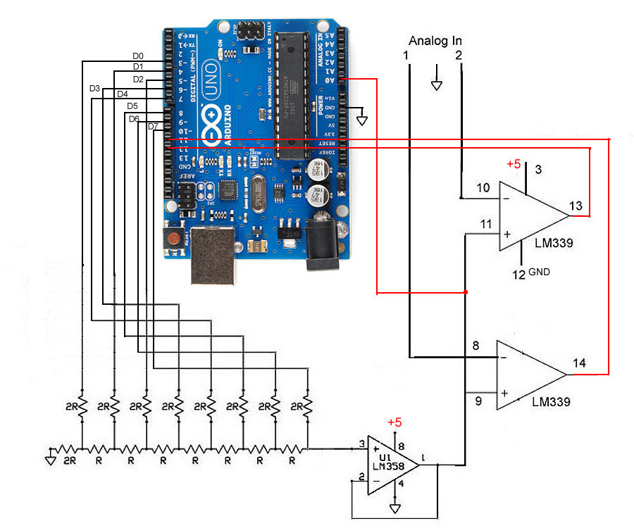
To implement our ADC, all we need to do is add a comparator to our DAC. We are actually going to add two of them, because later on we will implement dual ADCs that share a single DAC. This is a common practice, with each ADC only requiring its own comparator.
It is probably appropriate to mention one other component of a "stand-alone" ADC. That component is the successive approximation register, which controls the successive approximation process. In our case here, we don't need one, as we are going to control this process with our Arduino software. Doing it in software not only saves us some hardware, it also makes it easier to see how the process takes place!
Here is the board containing all the required components:
And here it is connected to an Arduino Uno:
Our analog inputs are the unattached blue and orange wires, while the unattached white is the ground line for the analog inputs.
ADC ResultsHere is our ADC in single channel mode showing a 20 Hz sinewave produced by a signal generator and being displayed on Arduino's Serial Plotter.
There are actually two different single channel ADC programs. The first is slow_single_ADC, It uses a slow serial baud rate, and uses floating point math to convert the output of the ADC to its actual voltage. It also uses digitalRead() to read the comparator. For all these reasons, it only works up to about 100 Hz.
The other single channel ADC is fast_single_ADC. Here we have taken the serial speed to maximum 2000000 baud. We have removed the floating point conversion to voltage, and replaced the digitalRead() with direct port access. It is faster, but is still limited to about 1 KHz.
It turns out my hardware is pretty slow no matter which way we do things. One obvious reason is that we are using serial communication to output the results to Arduino's Serial Plotter. Even at its highest speed, it slows things down, But in addition, I had to add several microseconds of "settling time" between setting the DAC and reading the comparator. This is most likely due to parasitic capacitance from all those wires and the ADC/DAC board itself.
The overall effect is that an ADC read takes about 100 microseconds all together. That is pretty slow, and limits our measurement capability to about a maximum frequency of 1 KHz. We could, of course, clean everything up, make the wires shorter, etc. and improve the performance some, but the purpose here is to demonstrate the technique, not necessarily optimize it!
Dual Channel ModeAnd here is our ADC in dual channel mode showing a 10 Hz sinewave on channel 1 and an adjustable power supply being adjusted up and down on channel 2.
The program for dual channels is fast_dual_ADC. It is the same as fast_single_ADC, except it alternates between reading channel 1 and channel 2. We apply the same DAC to two different comparators, and measure the voltages on each. This means that the sampling rate is cut in half, but other than that, both programs work the same.
This demonstrates how, once you have one ADC, it is easy to create multiple ADCs, as long as you are not overly concerned about the sample rate.
ConclusionsWe learned the basics of how DACs and ADCs operate. There are other types of ADCs, much faster than the successive approximation method. But at least here we have gotten a general idea how they work and what some of the issues are with regard to accuracy, sample rate, etc.


Comments