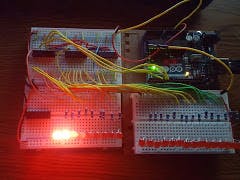
Back when I was going to electronics school in the 80's I built and installed a Night Rider lighting system in a friends camero using a bi-directional shift register to control the lighting effects. When I started experimenting with the Arduino and learned about how to control shift registers with the Arduino I wanted to simulate the Night Rider.
Pinout and Mode of OperationIn this project I use three shift registers to control 24 LEDs. The registers are connected together by taking serial out pin (pin 9) of the first shift register to the serial data input (pin 14) of the second register. Next you take the serial out pin (pin 9) of the second shift register to the serial data input (pin 14) of the third shift register.
The clock pin (pin 11) on all three shift registers are connected and driven by one output from the Arduino.
In this manner when you send the clock signal from the Arduino you will be causing the data to shift simultaneously in all three shift registers. Because a single call to the shiftOut() library function only shifts out one byte you will be calling it three times to update all three registers.
In my code I have a function "updateShiftRegister()" which takes care of setting the latchPin low, shifting out all 24 bits of my current led pattern, then setting the latchPin back high to update the LEDs.
This is the datasheet for the 74HC/HCT595:


_ztBMuBhMHo.jpg?auto=compress%2Cformat&w=48&h=48&fit=fill&bg=ffffff)

Comments