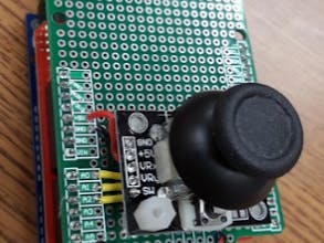
This shield provides the necessary connections between the joystick and the Arduino so that it can read the joysticks X, Y and Switch readings on it's analog inputs. I chose to mount the joystick on it's own proto shield instead of mounting it to the prototype area of my XBee shield.
Wiring and connectionsLooking at the project photo above, you can see three yellow wires that connect to A0, A1 and A2. These correspond to the VRx, VRy and SW outputs from the joystick.
In the video I mount the shield to an XBee Wireless shield then mount that to the Arduino that acts as the brain for this wireless joystick controller. The XBee shield has it's serial switch set so that it looks for serial data D2 and D3, requiring the use of the Software Serial library, leaving the hardware UART on the Arduino free for programming and debugging.
The Arduino program polls the status of the joystick every 40 ms (about 20 times a second) then transmits the X, Y and Switch readings over via the XBee wireless module to an XBee wireless module on a Sparkfun Redbot. The program on the Sparkfun Redbot receives the values then makes the necessary adjustment to the power and direction of it's left and right wheels causing the Redbot to go forward, backwards or turn.
UpdateControlling with one joystick felt kind of squirrelly, so I added a second one then adjusted the programming so one joystick was used for forward/backwards and the other for left right. This gave it much more stability and made it more fun to drive. Shortly after completing the build, Jeff Branson with Sparkfun sent me some better joysticks so I built a second shield. Here is a video I shot part way into the second build:
Here is a video of the Redbot in action using the new and improved dual joystick xBee controller!


_3u05Tpwasz.png?auto=compress%2Cformat&w=40&h=40&fit=fillmax&bg=fff&dpr=2)
Comments
Please log in or sign up to comment.