

Hardware components | ||||||
_ztBMuBhMHo.jpg?auto=compress%2Cformat&w=48&h=48&fit=fill&bg=ffffff) |
| × | 1 | |||
Software apps and online services | ||||||
| ||||||
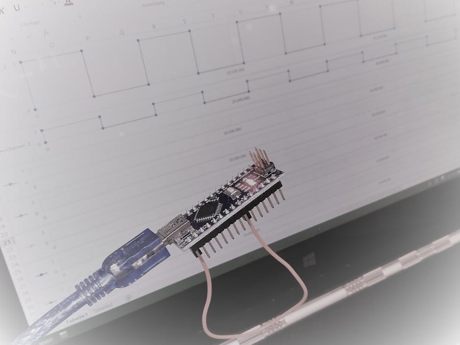
Did you ever ask yourself if ISP works correctly? Or is the PWM-output really correct? I first wanted to buy a digital oscilloscope to record the output of some signals to know what's really going on. Then I found out, that there are digital (or logical) analyzers and I thought, that I can manange to program this by my own. And this is the output of my work and I hope it is helpful to you. Simply follow the instructions on your Serial monitor (or below) and enjoy!
For testing purposes I included a frequency generator, which is also helpful to test other electrical parts.
Note: If you are using an older board with anATmega48/88/168, youneedtoadjustthevariablemaxSamplesatthebeginningofthesourcecode.
There are two modes: FastMode and DirectMode.
While using FastMode you need to send the number of samples to be recorded via SerialMonitor to the Controller (e.g. '140'). This amount of samples will be recorded and printed afterwards. It is possible to detect about 100, 000 samples per second, however (as SRAM as limited) only 300 samples can be recorded.
While using DirectMode, each detected Sample will be printed directly to the SerialMonitor. It is possible to detect about 200 samples per second without running into a buffer overflow. Faster samplerates will lead to a buffer overlow and recording will be stopped automatically.
To call DirectMode, you need to send a '0' via SerialMonitor to the controller.
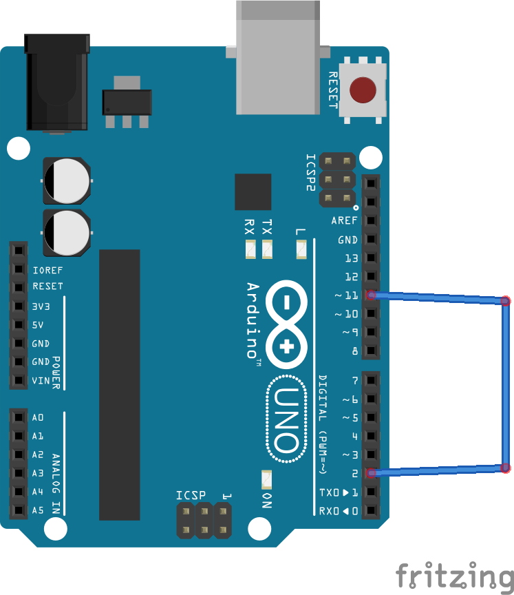
There are six channels that can be recorded (pins 2 - 7). To set the supervised channels, enter e.g. 'c245' to observe pins 2, 4 and 5. The input pins are internally connected to pull-up resistors. It doesn't matter how many channels are observed, the possible recordable samplerate is not effected.
The current recording can be aborted by sending 'x' to the controller. The recored samples will be printed out.
It is possible to call a frequncy generator on pin 11. To enable it, you need to send e.g. 'f123.456' via SerialMonitor, where the number represents the frequency (in this case 123.456 Hz). A frequency between 0.007451 and 8, 000, 000 Hz can be chosen, however not infintely variable. The exact output frequency is printed below. The maximum recording speed (samplerate) is not influenced by the frequency generator.
All inputs need to be completed with a 'LineFeed' (see setting in SerialMonitor). You can copy the output for example into Microsoft Excel to plot diagrams and analyze the digital signals. I created an Excel file with macros to import the data from your clipboard: DigtialAnalyzer.xlsm (Be aware that.xlsm-files can countain malicious software! Check the VBA-Code (Alt + F11) to see that my file only copies the clipboard content to the worksheet and does some further calculations).
Set up a baudrate of 115, 200 for the serial communication.
LimitationsIt is possible to record up to 100, 000 samples / second. However, it is only possible to record 300 samples in total until the internal SRAM runs out of memory.
InternalsThe input pins are internally connected to pull-up resistors.
This programm uses Timers1 and 2, Timer0 is disabled. Therefore millis(), micros() and delay() won't work. I chose to do this to make this a most possible lightweight program with best performance.
Timer1 is used to measure the time of the input signals with a prescale of 8, which leads to an accuracy of 0.5us.
Timer2 is used for the frequency generator. Its prescaler is adjusted according to the desired frequency in order to reach the closest possible output frequency. For frequencies higher than 30.5 Hz the PWM-mode CTC is used to toggle the output pin 11. This does not use any CPU performance. For slower frequencies a overflow interrupt routine is executed to toggle the output pin, which doesn't use much CPU as it occures only quite rare.
Look aheadI'm planning to extend the Excel-file to directly communicate with the Arduino.


Comments