For people, especially elderly people, experiencing a fall unnoticed by others can have severe health consequences. Besides the obvious possibility of injuries as direct result of the impact, further health damage is often the consequence if medical aid and treatment cannot be obtained within a short time. The accident situation gets aggravated, if the person is no longer able to call for help due to immobility or unconsciousness. A lot of research has been done and many articles have been published on the topic of building devices for fall detection using accelerometers. This project makes use of some of this knowledge to implement a very simple solution as a proof of concept featuring the Sony Spresense with the Spresense LTE extension board.
The project documentation is also available at the Git repository on GitHub.
ComponentsHardware- Sony Spresense main board
- Spresense LTE extension board
- MPU-6050 3-axis accelerometer and 3-axis gyroscope sensor e.g. the GY-521 MPU-6050 3-axis gyroscope and acceleration sensor board
The Sony Spresense is a low-power board computer for the IoT that is equipped with a GPS receiver and supports High-Resolution Audio codecs. It's a compact development board based on Sony’s power-efficient multicore microcontroller CXD5602, which to develop applications in short time and is supported by the Arduino IDE. Main features:
- Integrated GPS - The embedded GNSS with support for GPS, QZSS and GLONASS enables applications where tracking is required.
- Hi-res audio output and multi mic inputs - Advanced 192kHz/24 bit audio codec and amplifier for audio output, and support for up to 8 mic input channels.
- Multicore microcontroller: The Spresense is powered by Sony's CXD5602 microcontroller (ARM® Cortex®-M4F × 6 cores), with a clock speed of 156 MHz.
For more details see here.
Sony Spresense LTE Extension BoardThe Spresense LTE Extension Board adds LTE connectivity to the Spresense main board and carries an onboard antenna and a nanoSIM cardholder. Employing the Sony ALT1250 chipset, it ensures compliance with LTE-M (LTE Cat-M1) and NB-IoT communication standards. It also extends the interfaces of the Spresense main board with multiple mic inputs, a headphone jack, and a microSD card slot. The Spresense main board and the Spresense LTE extension board are connected by a board-to-board connector.
For more details see here.
MPU-6050 Six-Axis (Gyro + Accelerometer) MEMS MotionTracking™ DeviceThe MPU6050 sensor chip combines a 3-axis gyroscope, a 3-axis accelerometer and a digital thermometer. The built-in hardware DMP (Digital Motion Processor) unit facilitates the conversion of processed data from all three sensors to a specific position relative to the Earth, thus relieving the microcontroller. It features three 16-bit analog-to-digital converters (ADCs) each for digitizing the gyroscope and accelerometer outputs. For precision tracking of both fast and slow motions, the parts feature a user-programmable gyroscope full-scale range of ±250, ±500, ±1000, and ±2000°/sec (dps) and a user-programmable accelerometer full-scale range of ±2g, ±4g, ±8g, and ±16g.
For more details see here
Software / Libraries / Services- Arduino IDE
- Spresense Arduino Library (LTE, RTC, SDHCI, File etc.)
- Adafruit MPU6050 library
- ArduinoHTTPClient library
- Signal Messaging App
- CallMeBot API
Description: see below.
Additional components- MicroSD card
- SIM (nano form factor)
- Wires
The idea for this project is, to use an accelerometer and gyroscope sensor, to detect a fall situation and to alert another individual or organisation via LTE.
It is assumed this prototype is part of a device (Spresense board(s) + sensor + battery + casing) that can be worn e.g. clipped to a belt of a person.
The fall detection algorithm focuses on the total acceleration – the "sum" of the acceleration of 3 axes – defined as
It is based on the concept that during a fall, a person experiences a momentary freefall – a reduction in acceleration toward zero, followed by a large spike in acceleration on the impact and a sudden change in orientation (e.g., from standing to lying) – all this within a time interval of one second or less.
If all these three events (free fall, impact and orientation change) in acceleration have been observed within a short time interval (a second or less), it is assumed that the device has observed the user falling down.
While the free fall and impact events can be easily derived by just comparing the total acceleration against given thresholds, detecting a sudden orientation change can be observed in more simple way by regarding the magnitude of the rotation speed obtained from a 3-axis gyroscope.
If a fall has been detected an alert message is sent to person or an organisation who then can look after the monitored individual and provide help if necessary.
The LTE connectivity provided by the Spresense LTE extension board and the integrated GPS of the Sony Spresense main board enables the device to send an alert message with position data from locations indoor & outdoor (out of range of WiFi connectivity).
For this prototype the alert message is sent via Signal Messaging using the CallMeBot API.
Signal is a cross-platform centralized encrypted instant messaging service developed by the non-profit Signal Foundation and Signal Messenger LLC. Users can send one-to-one and group messages, which can include files, voice notes, images and videos. It uses standard cellular telephone numbers as identifiers and secures all communications to other Signal users with end-to-end encryption.
CallMeBot provides an easy to use free API to send text messages (like notifications) and images through various messaging applications (like Signal, Telegram, WhatsApp etc.)using one simple API call from any device (Home Assistant, OpenHab, ioBroker, IFTTT, etc...).
To use the API for sending messages to a recipient, it is necessary to obtain an API key for this recipient. This can be easily achieved by sending a specific message to the CallMeBot service from the receiving app/device:
For more details about the service and the registration process see here.
ImplementationPrerequisitesThis implementation is based on the Spresense Arduino Library, so it's required to setup the environment as described in the Spresense Arduino Library Getting Started Guide.
Additionally, the following libraries need to be installed, preferably using the Library Manager of the Arduino IDE:
- The Adafruit MPU6050 library for accessing the MP6050 sensor and
- the ArduinoHTTPClient library for making the API call to CallMeBot via HTTP(S).
For the LTE connectivity an appropriate activated unlocked SIM (with PIN deactivated) is required.
For the communication with the CallMeBot service via HTTPS it is necessary to store the root certificate of the CallMeBot web service on a FAT formatted microSD card. For details about the procedure refer to the example here and the guide here. The current valid root CA for the CallMeBot API service - the ISRG Root X1 CA - can also be found here.
WiringThe MPU6050 module communicates through I2C with the default default I2C address 0x68. For details about using I2C with Spresense LTE extension board and the Spresense Arduino Wire Library refer to the Spresense Hardware Documentation and the Spresense Arduino Library Developer Guide - Wire Library
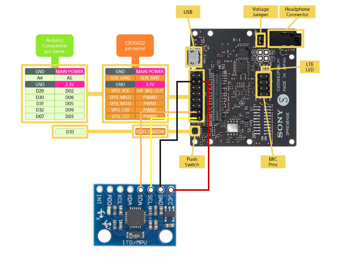
The MPU6050 is connected to Spresense LTE extension board as follows:
The SDA connector on the MPU6050 board is connected to pin D03 (PWM3) on the Spresense LTE extension board and the SCL connector is wired to pin D09 (PWM2).
CodeThe code for this project is split into multiple separate sketch files for better readability:
- accelerometer_and_gyroscope.ino
- app_settings.h
- fall_detection.ino
- lte_web_client.ino
This sketch file contains code for the initialization of the MPU6050 board and for obtaining the sensor readings for the 3-axis accelerometer and the 3-axis gyroscope.
app_settings.hThis file contains the parameter settings for the application:
- thresholds for the fall detection function:
- APP_FD_DETECTION_TIME_INTERVAL in milliseconds
- APP_FD_FREE_FALL_ACCELERATION_THRESHOLD in m/s2
- APP_FD_IMPACT_ACCELERATION_THRESHOLD in m/s2
- APP_FD_ORIENTATION_CHANGE_THRESHOLD in rad/s
- parameters for the CallMeBot API:
#define APP_SEND_MESSAGE_HOST "api.callmebot.com"
#define APP_SEND_MESSAGE_PORT 443
#define APP_SEND_MESSAGE_PATH "/signal/send.php?phone=<phone number>&apikey=<api key>&text=Alert%3A%20Fall%20detected%21"
#define APP_ROOTCA_FILE "isrg_root_x1_dst_root_ca_x3_.cer- settings for the LTE connectivity (APN, user, password etc.)
This is the main sketch. It contains the "application logic"
void loop()
    {
    float accX, accY, accZ;
    float gyrX, gyrY, gyrZ;
    bool fall_detected;

    read_acceleration_and_rotation(&accX, &accY, &accZ, &gyrX, &gyrY, &gyrZ);
    fall_detected = fall_detection(accX, accY, accZ, gyrX, gyrY, gyrZ);

    if (fall_detected)
    {
        send_request();
    }
}
and the fall detection function:
bool fall_detection(float accX, float accY, float accZ, float gyrX, float gyrY, float gyrZ)
{
    bool freeFallTrigger, impactTrigger, orientationChangeTrigger;

    // Thresholds and interval
    const unsigned long detectionInterval = APP_FD_DETECTION_TIME_INTERVAL;
    const float freeFallThreshold = APP_FD_FREE_FALL_ACCELERATION_THRESHOLD;
    const float impactThreshold = APP_FD_IMPACT_ACCELERATION_THRESHOLD;
    const float orientationChangeThreshold = APP_FD_ORIENTATION_CHANGE_THRESHOLD;

    // Last detection time for each trigger
    static unsigned long timeFreeFall = 0;
    static unsigned long timeImpact = 0;
    static unsigned long timeOrientationChange = 0;

    unsigned long currentTime = millis();

    // Total acceleration and rotation for all three axes
    float totalAcc = total(accX, accY, accZ);
    float totalRot = total(gyrX, gyrY, gyrZ);

    // Free fall detected: Total acceleration below defined threshold
    if (totalAcc <= freeFallThreshold)
    {
        timeFreeFall = currentTime;
    }

    // Impact detected: Total acceleration above defined threshold
    if (totalAcc >= impactThreshold)
    {
        timeImpact = currentTime;
    }

    // Orientation change detected: Total rotation above defined threshold
    if (totalRot >= orientationChangeThreshold)
    {
        timeOrientationChange = currentTime;
    }

    // Events triggered within defined time interval?
    freeFallTrigger = (currentTime - timeFreeFall < detectionInterval);
    impactTrigger = (currentTime - timeImpact < detectionInterval);
    orientationChangeTrigger = (currentTime - timeOrientationChange < detectionInterval);

    // Fall detected: All three triggers occured within defined time interval.
    return freeFallTrigger && impactTrigger && orientationChangeTrigger;
}This sketch part is based on the example Checking HTTP Client behavior using the TLS protocol in the Spresense Arduino Examples & Tutorials The send_request() function makes the HTTP GET call to the CallMeBot API service to send the predefined message.
TestDevice caseFor testing the device has been put into a 3D-printed case based on The sample case for Spresense LTE extension board:
Application startup:
Fall detected & alarm:
Detection mode:
Alarm:
The dev branch of this project contains additons/changes for a new feature GNSS positioning:
Additional sketch file: gnss_positioning.ino
This sketch part is based on the example gnss.ino in the Spresense Arduino Library Developer Guide. The function update_gnss() has to be called by the loop() procedure to obtain valid position data from the GNSS modul at regular intervals without blocking.
Modifications:
- Two new parameters have been added to app_settings.h for (de)activation of the positioning feature and to control the position update cycle time.
- In ltw_web_client.ino, the send_request() function has been modified to take a parameter for the message text to be send.
- fall_detection.ino: If the feature is activated, the position is updated at regular intervals and appended to the text message when sending an alarm.
Test:


Comments
Please log in or sign up to comment.