


Hardware components | ||||||
 |
| × | 1 | |||
 |
| × | 5 | |||
 |
| × | 1 | |||
 |
| × | 1 | |||
 |
| × | 1 | |||
 |
| × | 1 | |||
| × | 1 | ||||
| × | 1 | ||||
 |
| × | 3 | |||
 |
| × | 40 | |||
| × | 5 | ||||
| × | 1 | ||||
| × | 5 | ||||
| × | 1 | ||||
 |
| × | 12 | |||
| × | 1 | ||||
| × | 1 | ||||
| × | 1 | ||||
Software apps and online services | ||||||
 |
| |||||
Hand tools and fabrication machines | ||||||
 |
| |||||
 |
| |||||
CUSnek slithers according to a horizontal sinusoid and follows a path. The team designed, developed, and manufactured the following: code for controlling movement, sensing the environment, a PCB design and wiring harness, and a custom mechanical design for the snake which was 3D printed. Due to time limitations the PCB is held on a tether rather than integrated into the body of the snake.
Head
The head holds the reflectance sensor, ultrasonic sensor, and the magnetometer. The head was custom designed and 3D printed using PLA. The head includes two wheels on either side to reduce the friction coefficient. Wheels are attached to the on ends of a toothpick. The body of the snake houses the servos to push the head forward.
Due to environmental weather shift, the PLA expanded more and required additional sanding to accommodate the ultrasonic sensor.
Body
Servo Horn To get the sizing right, the team made a prototype to determine the dimensions for attaching the servo horn to the body
Wheel Axel To get the sizing right, the team made a prototype to determine the dimensions for 3D printing the holes for the toothpick wheel axels to fit into.
Wheels Early design for the body featuring wheel design that would didn't have enough grip.
Improved wheel design with bands to provide more grip for the wheels.
Electrical Design
The IMU, reflectance sensor and servo motor have the same input voltage of 3.3V, but the servo motor drive generates a lot of switching noise on the power rail, so we isolated the supply voltages to avoid fluctuations in the power rail.
For debugging and testing we included several test points in the schematic design, LED indicators, and module isolation switches for the signal output and input of the circuit board.
A 1000uF decoupling capacitor removes excess noise for the servo motor power.
Wire Management
Part of electrical team was responsible for designing an effective cable harness. Ideally, this one harness would act as the spinal cord of the snake connecting to the ultrasonic sensor in the head, then it would branch off, connecting to each servo down the body. Eventually, it would reach the brain which would be the PCB mounted on the MSP.
On the PCB, there are 4 connections to this harness that required special splicing of the cables:
- Reflectance_&_IMU_VCC (2 to 1) - 1 female, 1 male
- Sensors_Common_GND (3 to 1) - 2 female, 1 male
- Servo_VCC (5 to 1) - 5 male
- Servo_GND (5 to 1) - 5 male
The procedure for making those splicing cables is as follows:
- Cut listed jumper wires to about 3” and then strip one end about .5”.
For each cable, the needed jumper terminations (male/female) are listed above. Leave those sides attached. - Cut a wire to approximately 3 feet and strip both ends about 0.5”.
- Twist together the exposed ends of the jumper wires with an exposed end of the 3’ long wire.
- Solder connection.
- Terminate the connection with heat shrink.
** The example above is a prototype and shows how to solder the two ends together. The splicing cables we actually used jumper wires cut to 3 inches and the connecting wire cut to 3 feet.
Pin Mapping
Below is a detailed mapping of the pins as well as where in the harnessing they would be connected to their respective pins. This was both something PCB production required excellent documentation on and communication between the electrical and firmware teams was vital for this process.
Electrical Component Testing and other Trade Studies
The final thing that the electrical team was tasked with was more or less making sure every necessary component and subcircuit worked on the PCB and that the nervous system of the snake worked. As a result, transient testing as a whole was completed to quantify the 3.3V and 5V regulators' transients when hooked up to their loads. Furthermore, pretty much every load had an electrolytic decoupling capacitor circuit that also was incorporated in the transient testing. The purpose of the decoupling capacitors was to filter any non-DC noise to ground away from any inputs and outputs of sensors and the motors. We had a 7.4V power supply at our disposal and the regulators could handle 3A and 800mA respectively. However, we set the power supplies to 6.3V because we had originally planned to integrate a reverse polarity safety circuit on the PCB that would've had a 1.1V drop across it before reaching any of the voltage regulators. We ended up not having that, so our transient testing became although not obsolete, pretty inaccurate. Either way, for the 5V regulator. the MSP and ultrasonic sensors were the only things that required 5V, and the other sensors were powered via the MSP's 3.3V ports. The following is the result of the 5V transient testing:
For those sensors that were powered by the MSP, there appeared to be a 4 ms delay between the 5V rising edge and the 3.3V rising edge - perhaps something to do with the internal circuitry and time constants of the MSP's own drop-down voltage regulator. This information would be vital for the software team had there been more time for precise calibrations, and appropriate sensor response times. Indeed the wiring of everything had very non-negligible response times when powered and when unpowered.
For the 3.3V regulator test with the motors, it was found that the charging time constant was about .00278 seconds, and the discharging time constant was about 0.61 seconds.
Other trade studies included I2C cable length studies that ended up not being relevant because the IMU that communicated using I2C protocol was never used. Please see electrical CDR for more information on that.
There were also trade studies on the polarity circuit and labeling on the PCB. Please see CDR for more information.
Power
The final task of the electrical team was to develop power budgets. This process was mostly just manual reading and datasheet referencing and we prepared a worst-case scenario where max forward current and voltage were used in every component we had. From that, we estimated that roughly 11 minutes on a full charge of our 7.4V dual-cell lipo battery was the life expectancy before needing to recharge.
The firmware team wrote the code for the movement and state machine of the robotic snake project. To start the snake’s movement, a button on the MSP is pressed. The snake responds to walls in its path using the ultrasonic sensor. When a snake encounters a wall between 15 and 16 cm away, the snake turns right to avoid the wall and keeps moving. Walls are positioned around the snake’s path to direct its movement.
The firmware section is divided into three sections: state machine, movement, and the sensors.
State Machine:
The state machine consists of eight possible states. These states are initial, forward, right turn, left turn, reverse right turn, reverse left turn, reverse, and stop. The state machine initializes in the “Initial” state and the state is changed to “Forward” by pressing a button on the MSP. Due to time constraints, the reflectance sensor was scrapped from the final design. Although it has been removed, the state machine still shows the functionality with the reflectance sensor, as well as is still functional without it. In the diagrams below, the snake will be programmed to a certain route to display all functionalities. This route will allow the snake to go forward, turn left and right due to reflectance sensor interrupts, reverse and stop due to objects blocking its path, and return home in any given state. Since the snake has a predetermined route as shown below, the counter in the state machine determines if the snake will be going left or right at a given reflectance sensor. The obstacle avoidance is programmed to sense an object with the ultrasonic sensor, reverse for a couple of seconds, turn right, go forward, and turn left. The snake will continue this process until it is past an object. The “Go Home” functionality is initiated by pressing the same button which was pressed to begin the state machine. The movements are then reversed for the same amount of time in which they were originally done. This will allow the snake to do the same route backwards and return to its home and then set the state to initial to be ready to go again.
Movement
The snake moves in a sinusoidal motion along the ground. The snake has 8 movement states: 1. Stopped, 2. Moving forward, 3. Moving in reverse, 4. Turning right, 5. Turning left, 6. Turning right while moving in reverse, 7. Turning left while moving in reverse, and 8. calibrating. The calibration state sets all the motors to be at 90 degrees, and is used to position the arm relative to the motor body. The state of motion is determined by the desired sensor inputs implemented in the state machine. The calculations for the sinusoidal movement are determined by various inputs. The first and fourth sensors correspond to one calculation, the second and fifth sensors correspond to a second calculation, and the third sensor corresponds to a third calculation.
Once the CCR[x] values have been set, the program uses interrupts to generate the PWM waveforms for each motor. At the start of the period, all output pins associated with the 5 motors are turned high. When the interrupt of the associated motor is triggered by the CCR[0] count value hitting that CCR[x], the pin(s) associated with that interrupt are set low, thus ending the ‘PWM high’ signal for that period. This PWM sets the degree of the motor, as calculated by the desired degree in the original calculation and represented by degree_val1.
Right and left turns are implemented by also following the sine wave, but by adding a right- or left-turn offset to the degree calculation as shown by degree_val. In order to prevent jolting movement, there is a brief period of time that the offset ‘ramps up’ to the full right/left offset value, then the sinusoid continues for most of the period with the degree value plus the right/left offset. In the final moments of the period, the offset value ramps back down from the full right/left down to 0, to continue forward movement once more.
Right and left reverse turns are implemented by combining the reverse movement and the right and left turning movement, the (3600-wavepoint_counter) term is used when calculating the frequency in the cosine, and the right and left offset values are added to the overall degree calculation to implement a turn.
Each of these states was manually entered for testing, and then the motion was verified after being integrated with the final mechanical body design and electrical PCB and wiring harness design. The sinusoidal movement moved the snake forwards, and in response to an ultrasonic sensor trigger, the snake began turning right.
Sensors
For navigating the movement of the snake through our state machine, it relies upon two sensors for detecting obstacles. The first observing the forward direction through an Ultrasonic Sensor, as well as managing position from above, using a Reflectance Sensor.
The primary focus of each is to first, allow us to detect walls as the Snake approaches via Ultrasonic Sensor mounted horizontally, observing in front of the snake's current direction. Once a certain distance is observed, it allows our code to indicate a state change for implementing a turn or reversing. In a similar fashion, the basis for the Snakes movement void of obstacles is reliant upon a black square. Attaching the reflectance sensor beneath the Snakes chassis allows for detecting the color change between the floor and the posted black squares. Allowing the code to again implement any necessary state changes.
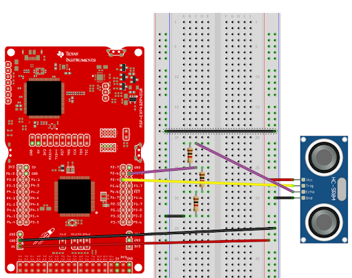
Ultrasonic Sensor Code Development - Breadboard Circuit
Located within the MSP432 for this code to run are the following pin maps.
Vcc -> MSP432 5V Supply
Gnd -> MSP432 GND
Echo -> PIN 2.6
(Used with a voltage divider of 3 equal resistance Resistors in series. Drawing voltage after 1st Resistor.
Trip -> PIN 2.7
Sensor's trigger distance is configured within the code, allowing for setting ranges, minimum values and maximum values for detection. As is the case with an Ultrasonic sensor, calculations are made converting from the speed of sound.


Comments
Please log in or sign up to comment.