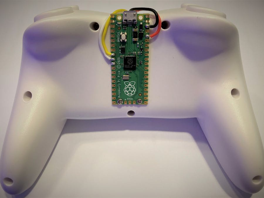
This project is to convert an old Wii Classic Controller into an emulator of an HID keyboard. Each button or action can be mapped into a key press. This is done by using a Raspberry Pi Pico with CircuitPython's HID library. It can easily be modified to do key sequences extremely fast (faster than any human can with their hands), it can be adjusted for games where button smashing is required (don't use it on online competition games).
The reason I built it is to control a mobile robot. The robot requires certain ASCII character in order to perform several functions. These characters are sent through SSH. So, this project can send all the commands to the robot at a steady rate to make the motion of the robot be in "real time".
The way this classic controller used to communicate with the Wii-Remote is through the I2C protocol, the "wii-mote" would initialize communication with the classic controller. The wii-mote would receive data encrypted packages from the classic controller.
I request the data packages with the Raspberry Pi Pico in such a way that the classic controller will release the data unencrypted. This is done to not waste CPU cycles decrypting the packages.
Preparation for Raspberry Pi PicoIn order to do this project, CircuitPython and its libraries need to be installed on the Raspberry Pi Pico. The steps are as follows:
- Download CircuitPython for Rasberry Pi Pico from the circuitpython page: https://circuitpython.org/board/raspberry_pi_pico/. In my project, I installed version 7.x The extension of the file will be.uf2
- Press and hold the boot button on the pico and connect it to the PC, you will get the window bellow.
- Copy and paste the.uf2 file into the RPI-RP2 directory
In the image below, you can see the content of the pico board after the transfer of the file has concluded and the pico has rebooted on its own.
- Go to this link and Download the libraries that match the version of CircuitPython that was installed: https://circuitpython.org/libraries
- Open the zip file that was downloaded. Then find the lib folder. Inside the lib folder find the adafruit_hid folder. Copy it.
- Inside the CIRCUITPY drive, open the lib folder and paste the adafruit_hid library.
- Download and install Thonny from this site: https://thonny.org/
- Open Thonny while the pico still connected.
- On the toolbar go to Run->Configure interpreter.. and on the drop down menu "Which kind of interpreter should Thonny use for running your code?" Select: CircuitPython (generic)
- Under "Port" select the USB Serial Device, if more than one, select the one that belongs to the pico board.
- Download the code from GitHub: https://github.com/eftl93/rpi2040_HID_wii_classic_controller and extract the files.
- On Thonny, look for the "folder" icon to open a CircuitPython file. A dialog will open, click on "This computer". Find the "main.py" file inside the downloaded folder
The algorithm for this code can be explained in this flowchart:
- After the source code has opened, go to the toolbar and click on File->Save as... on the windows that opens click on "CircuitPython device"
- Save it with the file name: code.py
- Once it has successfully save, close Thonny. Then unplug and plug the pico.
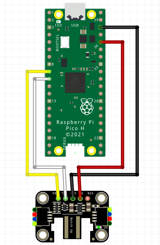
- Solder the wires to the pico according to the diagram below:
- Disassemble the controller
- On the PCB, solder the cables coming from the pico. Also solder a.1uF capacitor between GND and VCC to add stability. Pull up resistors are not necessary to add since they are built in on the board already.
- Put all the pieces back together
To prototype on a breadboard or to not disassemble the controller, you can use an adapter to connect to the end of the stock cable. Also the Raspberry Pi Pico will need to have header pins soldered on it. Then, you will have to use jumper cables to connect the lines together: On the adapter the "-" pin goes to GND on the pico, the "+" goes to 3.3V, "d" goes to SDA, and "c" goes to SCL. I found that using this method causes random disconnections.
To test the device:
- Connect the pico to the computer
- Open a text editor
- Press the "home" button on the controller to activate "keyboard" mode. The green LED on the board will light up.
- Move the joysticks and press the buttons to see the strings changing.
- Press the "home" button again to de-activate "keyboard" mode. The strings will stop typing and the LED will turn off
Conclusion
This project can be adapted for different uses, for example, you can 3D print Keypad with mechanical switches connected to the GPIO of the pico, and have the pico send key combinations such as "alt+f4" or "ctrl+c" to create a custom special command pad.


Comments
Please log in or sign up to comment.