Last article update:
2018-07-31: added the CAD files
2018-07-24: added the schematic and programming section
NOTE: The provided Aduino sketch is custom made for my situation but adaptable for your specific need. So feel free to use it but you do need to change the sketch!Why This Project?
You can buy a pendant for your CNC machine, but I built my wooden CNC machine so why not make my own pendant?
Besides that, a regular pendant for my controller board would cost 100 euros and have only 2 buttons and a handwheel.
My pendant has 23 buttons with up to 6 functions per button and a handwheel.
One comment could be, "it's large and heavy!" But in practice, it unexpectedly proved to be very handy to have a pendant which stays put when turning the handwheel...
The beauty of the Arduino with a 32u4 chip (not all model have this chip) is the ability to emulate a keyboard and/or mouse. When you connect the Leonardo to a pc, it 'sees' a keyboard. Great!
So when you program the Arduino, add some switches to it and connect it to a PC or Mac, you can sent (multiple) keystrokes/mouse movements to the computer bij pressing a button. As I mentioned, 23 buttons/6 functions per button = many options..
It all depends on the use of the right library for the Arduino sketch! After hours of searching I finally found a great library which I included on this page: Clickbutton.
With this library, you get these possibilities for each (momentary!) button:
- Single click
- Double click
- Triple ckick
- Single click and hold
- Double click and hold
- Triple click and hold
Also you get debounce functionality in the Clickbutton library which is important.
you can adjust the timings for each button but standard timing are >= 250ms to recognise a click and >= 1000ms to recognise a button hold.
Just an excerpt from my sketch for the 3 function X axis button (key 13):
if (button[13].clicks != 0)
 {
   switch (button[13].clicks)
   {
     case 1: // Single click
       // Handwheel on X
       shortcut_HANDWHEEL_X();
       break;
     case 2: // Double click
       // Zero X
       shortcut_ZERO_X();
       break;
     case 3: // Triple click
       break;
     case -1: // Single Click and Hold
       // USER MACRO 18: X-axis: goto work zero position G0 X0.0000
       press_ESC();
       goto_MAIN_MENU();
       user_MACRO_18();
       break;
     case -2: // Double Click and Hold
       break;
     case -3: // Triple Click and Hold
       break;
   }
}I chose to use mahogany wood for the pendant enclosure. I love to work with wood and the look and feel is wonderful. Also this way I could make a truly custom case which is not always possible with a ready made ABS type case you can buy for 20-50 euros.
The drawing was made with the Vectric Cut2D software. I'm glad I invested in this software package because it made the CNC learning curve a lot less steep and more fun. It also helps you to design double sided jobs very easily.
After sanding a little, the wood got many layers of clear varnish.
Feedrate in this video:
2400mm/min (~ 94"/min) of 40mm/sec. (~ 1.57") with a cut of 3mm (1/8") at the time
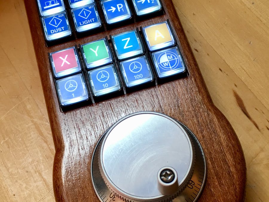
The SwitchesThe switches are great. They are the momentary type, except for the switch which I use to turn on/off the LEDs. You can put a label behind the clear top cover and if you want, you can lit the switch with the build-in LED.
I used a 1KΩ resistor per switch, using 2mA at 5Volts.
Here is a video with dutch audio, only to let you hear the sound the switches make. My comments are not important. I did say that the switches are a bit loud but at least you know when you pushed them ;)
One downside of using these switches is that they need a rather high or 'thick' enclosure. The wood thickness was 21mm (0.82" or 53/64") for the top AND bottom part. after machining, the total thickness of the pendant is 36,5 mm (14,37 or 14 3/8 inch)
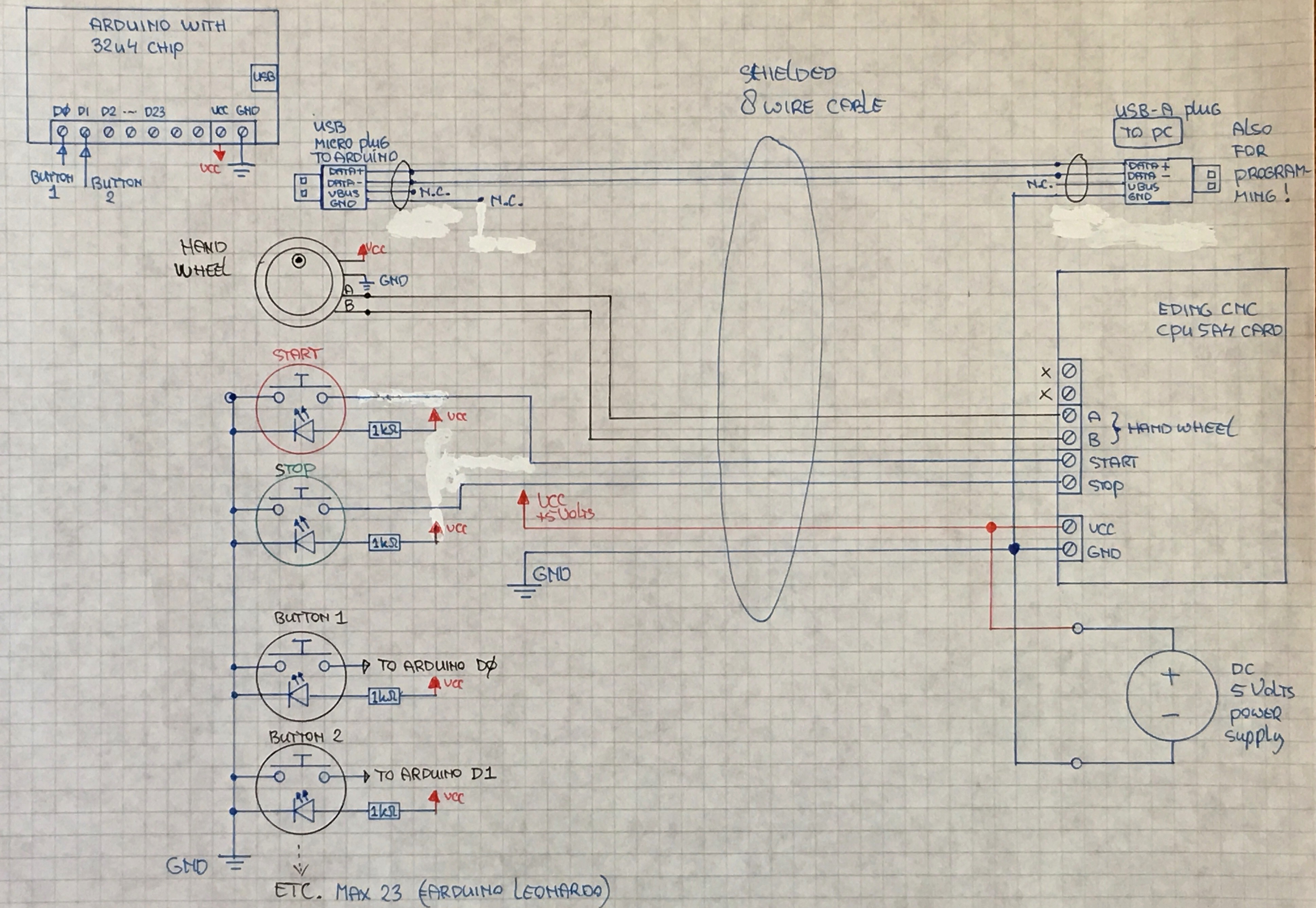
Connecting the switches is so easy... I use the Arduino build in pull-up resistors so all you have to do is connect one side of all the swiches to ground and the other side to the Arduino inputs.
The Switch LabelsFor labeling the switches I used a high quality Poly-Vinyl sticker for my color laserprinter. (Also available for inkjet printers). Printing on regular paper was no option because you do see the structure of the paper very good when lit.
Then I took off the transparent caps from the switches and put the labels on the piece of plastic underneath it.
The icons are the same as used in the Eding CNC software which is included with the hardware when you buy it. I just copied the JPEG icons from the software directory and I changed some in a graphics program to customise them for my need.
The HandwheelWell this one is a standard 60mm 100PPR 6 Terminal Eletronic CNC Hand Wheel
So 100 pulses per rotation, in most CNC software you can edit this value.
The ElectronicsAs an HID (Human Interface Device), I used an Arduino Leonardo microcontroller.
This microcontroller board has been discontinued but I could buy it at several online shop. As an alternative you can use the Arduino Micro which uses the same 32u4 chip.
This way I could mimic keyboard strokes and control many functions of the CNC machining software, in my case Eding CNC.
The Arduino Leonardo has 23 input pins so more than enough. As said, you can assign 6 functions per button.
Total power consumption is 150mA with the key LEDs on.
Programming the Arduino microcontrollerTo program the Arduino, you need to leave the pendant connected to the CNC power supply and upload the new sketch using the Arduino IDE software. (See the note below) So you use of course the same USB plug which is used for emulating the keyboard.
If you want to use another pc (laptop) for programming, simply put the USB plug into the other PC and program the Arduino, again leaving the pendant connected and powered bij the CNC power supply
NOTE: I did not connect the USB 5 Volts (coming from the PC) to the pendant because I do not want two VCC sources, the PC USB connection and the CNC machine power supply. The PC USB GND does need to be connected so we have one common ground level.
Have fun making your own pendant!


Comments
Please log in or sign up to comment.