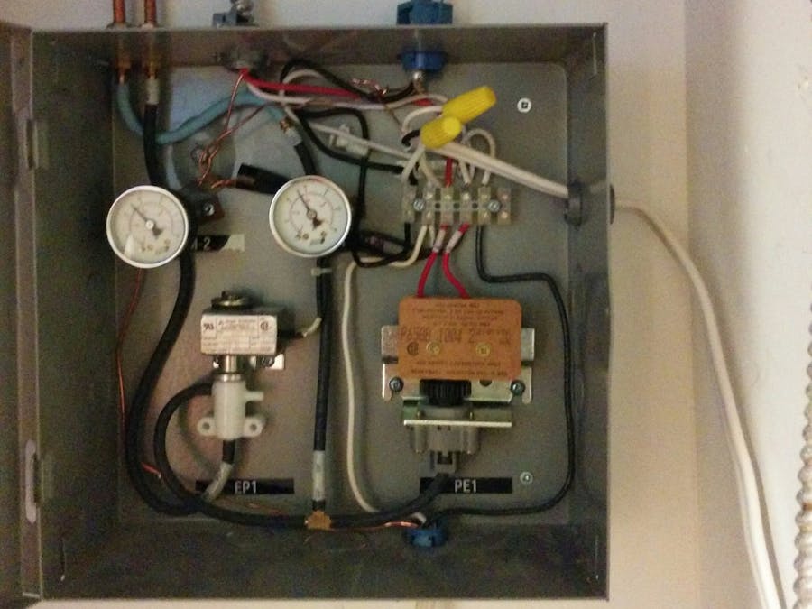
I've been living in my Condo for over 10 years now, and one of the most consistently frustration things about it has always been that I have been stuck with the 20+ year old semi-commercial pneumatic thermostat system.
Like the thermostats in an office building, this system uses air pressure to control switches that turn on and off both the heating and air-conditioning unit inside my unit.
So what are some of the issues that have annoyed me for years?
- A single fixed temperature, so if you want the house hot/cold when you get home, you have to leave it running all day while you are out.
- The system is pressure based, so as the temperature gets close to the setting on the thermostat, the system has a habit of 'shuddering' the air valves which can be pretty loud (especially when you are sleeping).
- The system isn't smart enough to know that when you set your temperature to 20°C degrees (68°F) in the summer, you don't want it to decide to turn the heat back on if it drops below that point (I ended up turning off the breakers for all the heaters during the summer).
- It is U-G-L-Y. I'm a techie kind of guy, and this thing just bugs me!
Last summer I was finally fed up with having to come home to a sweltering condo, and waiting for it to cool off. I ended up building my own Thermostat out of an ESP8266 and using it along with Blynk to control a simple relay, which I connected into the fan speed switch of the AC unit.
While that was a fun learning project, it only solved part of my problem, and also wasn't a viable long-term solution. I highly doubted the next person buying my condo would want to have a home-made thermostat to control their AC.
While doing research into how a regular home thermostat system works, I found this really detailed document: Themostatic Wiring Principles by Bob Scaringe PhD., P.E.
That gave me a whole new idea, why spend all this time trying to jury-rig the existing control system, when I could just simply replace it with a standard system that I could then control with a regular thermostat.
As you can see from the picture of the original panel above, the task did feel a little daunting at first. But after I spent some time identifying the source of all the wires, air tubes and where they came to/from, I was able to come up with a game plan for replacing almost all of the pneumatic system.
I opened up the old thermostat on the wall, and after disconnecting it from the air hoses, connected them together to bypass the thermostat airflow control. This now gave me a steady flow of air into the panel, and left the entire double gang box free as a location for my replacement thermostat.
Here is the view of the original panel, after I removed all the pressure switches and re-routed the air hose directly to the remaining air flow switch.
As you can see, there is one remaining air flow switch. That switch controls the air pressure that is used to open/close the valve attached to the chilled water line in the building. I decided to leave it alone. Although I was tempted to replace it with a 24V version, it ended up proving cheaper to just order an additional relay to control it.
Now that all the controls were mapped out, and I understood how a regular thermostat system worked, I was ready to build my 24V control system.
I had ordered 3 general purpose 24V SPST non-latching relays rated for switching 30A @ 250VAC, and a 24V transformer to power the entire system. I also purchased an 8"x8" enclosure to mount under the existing panel in the AC closet.
Here is me testing out the relay control system before I installed it into the panel. You don't really need to watch the video, unless like me, you enjoy the soulful sound of relays clicking.
The relays all have a common feed that goes to the transformer, and their other end is attached to a screw terminal block. I did that because I wanted it to be easy for me to attach the 5-strand thermostat wire to it after I installed it into the panel.
Here is the control system installed in the new enclosure, the system's transformer is powered by the 110V power line that also feeds the relays for the AC fan and the air flow switch. Now that they are on separate relays, I can use the fan with or without the chilled water active. This also gives me the option of running the fan to circulate warm air in the winter. The heater control relay controls only the power that goes to the 220V baseboard heaters. You can also see the brown 24V thermostat wire, which feeds into the bottom of the panel and into the terminal block.
And here it is all finished, with the thermostat installed (the larger face plate also covers the double-gang box).
I know, you DIY'ers are probably rolling your eyes at the Nest, but the rest of my condo runs on Google... And the whole point of the system was to be able to run any thermostat in it, when I leave I can now always take it with me, and leave behind a nice generic thermostat.
Anyhow, that is it for this project! Hope this inspires someone to find a way to solve a problem that has been bugging them. Depending on the feedback, I might post some of my other projects in the future.


Comments
Please log in or sign up to comment.