*******
Please visit https://proteshea.com/control-dc-fan-with-n-channel-mosfet-and-arduino-uno/ for a complete list of materials needed for this project.
*******
IntroductionIf you haven’t read our Getting Started Guide for the Arduino Uno Rev3, please read that first. Otherwise, continue reading. In this tutorial, we’ll be connecting an N-channel MOSFET to source current to a brushless DC fan. The fan requires 200mA at +5V which is over the max current that an Arduino Uno Rev3 (Uno) pin can source. If you consult the datasheet for the ATmega328, the max current per pin is 40mA. Going over the maximum current limit can damage the microcontroller so make sure you determine the load current before connecting any device to an Uno pin.
A MOSFET can be used for amplifying or switching signals – in this example, we’ll be using it as a switch. It consists of 3 terminals: gate, source, and drain (pinout is below). The N-channel MOSFET is a voltage-controlled device. There are two types of N-channel MOSFETs: enhancement- and depletion-type. An enhancement type MOSFET is normally off when the gate-source voltage is 0V, so a voltage must be applied to the gate for current to flow through the drain-source channel. A depletion-type MOSFET is normally on when the gate-source voltage is 0V, and thus current flows through the drain-source channel until a positive voltage is applied at the gate.
The 2N7000 N-channel MOSFET is enhancement-type so we must set the Arduino output pin high to provide power to the DC fan. The maximum current that a MOSFET can source varies, but the one I am using can source 200mA. Some MOSFETs can source up to 30-50A, and as a result, the size increases to be able to handle that amount of current.
NOTE: You’ll want to add a series resistor between the Uno output pin and the Gate of the MOSFET. This will limit the current to the gate since the Uno can only source a max of 40mA and the Gate may try to pull more than that. We recommend using a 220Ω resistor to limit the current to ~23mA.
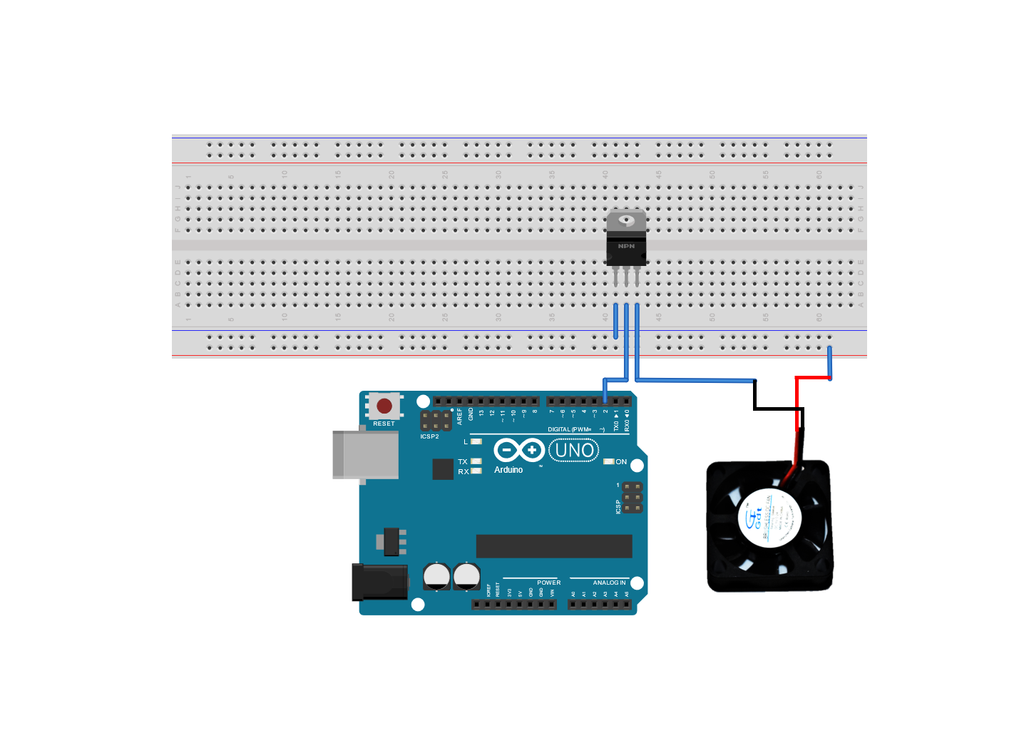
WiringI’m using a breadboard instead of Modulus since almost everybody has a breadboard. First, let’s place the N-channel MOSFET onto the breadboard – make sure that each lead has its own node. Tie the source pin to GND, the gate to Uno pin 2, and the drain to the black wire on the fan. The red wire of the fan gets connected to the positive rail on the breadboard.
If you haven’t mounted the Uno onto the prototyping area of the FuelCan, go ahead and do that. I placed the breadboard in the bottom storage compartment to limit the length of the jumper wires. We need to supply +5V and GND to the power and ground rails on the breadboard. Use the provided banana jack to test-lead clip cables to do so. You will need two male header pins to mount the test-lead clips to the breadboard side. Plug the Type A side of the USB cable into the USB1 receptacle and the Type B side into the Uno’s receptacle. Power up the FuelCan with the AC-DC power adapter.
Once the wiring is complete and the FuelCan is powered up, we can now load the sketch onto the Uno. It is quite simple compared to the previous projects. All the code does is toggle Uno pin 2 from low to high with a 5 second delay in between. When the pin is high, the fan turns on, and when the pin is low, the fan turns off.


Comments
Please log in or sign up to comment.