


Software apps and online services | ||||||
 |
| |||||
*******
Please visit https://proteshea.com/16x2-character-lcd-with-arduino-uno/ for a complete list of materials needed for this project.
*******
IntroductionHaving an LCD (Liquid Crystal Display) as part of your design offers many benefits. It can be used to display data acquired from sensors, create an interactive menu, or as a debugging tool. You can even create your own custom characters to display! In this project, we’ll be interfacing a 16×2 character LCD (in 4-bit mode) to the Arduino Uno Rev3 (Uno). This will require 6 digital output pins from the Uno to drive the LCD (4 pins for data and 2 pins for control).
Liquid Crystal Display (LCD)The LCD consists of 16 pins that are used for power, control, and data. It uses an industry standard Hitachi controller so the basic operation is similar across different vendors that sell them. They have both a 4-bit parallel and an 8-bit parallel interface. We’ll be using it in 4-bit mode instead of 8-bit. That means we have to send the higher nibble (1 nibble = 4 bits) first, then the lower nibble to send the byte of data required for each command or character. The most common LCD is a 16×2 or a 20×4 which means that it can display 16 characters on each of its 2 lines and 20 characters on each of its 4 lines, respectively. A pinout of the LCD is below.
NOTE: The LCD does not come with a 16-pin male header so you’ll have to solder one on.
Pin 1 and pin 2 are used to power the LCD and should be connected to GND and +5Vdc, respectively. Pin 3 is used to adjust the contrast – this will be connected to a 10KΩ potentiometer (pot) so the output voltage to pin 3 can be varied. The Register Select (RS) on pin 4 is used to either send commands when it is low, or data when it is high. Pin 5 is for Read/Write (R/W) and is used to read or write data from the LCD. The LCD has the capability to execute a program and display information which justifies the need for this pin. However, we will only be writing to the LCD, so we can ground this pin which will place it permanently in write mode. The next eight pins (7-14) are used to send the data. Since we’re using the LCD in 4-bit mode, D0-D3 (pins 7-10) are not used. Pins 15 and 16 are the anode and cathode of the LED backlight, respectively. We will need to use an external resistor in series with this backlight to limit the current. Otherwise, the LED could burn out.
The LCD has a timing diagram that must be followed to be able to send commands and character data. There are also set-up and hold times which also must be taken into account. This allows the signal levels to settle and ensure that pins are sampled at the right time. The diagram below shows the timing diagram for sending a command to the LCD in 4-bit mode. If we want to send the command to clear the display, we have to send 0000 (upper nibble) on the data bus and then send 0001 (lower nibble) on the data bus.
The diagram below shows the timing diagram for sending data to the LCD in 4-bit mode. For example, let’s say we want to send the character 1 to the LCD. The 8-bit ASCII equivalent is 0x30 or 0011 0000, so we would send 0011 on the data bus and then 0000.
You do not have to write your own driver for the LCD since there is a library that we can use called LiquidCrystal.h. The library is simple to use and allows us to input the specs of the LCD such as the number of columns and rows, and whether to use a 4-bit or 8-bit interface. We can also send data and up to 19 different commands.
Wiring the LCDWe are using the Modulus Canister to mount the LCD. Please watch the video below if you are using Modulus.
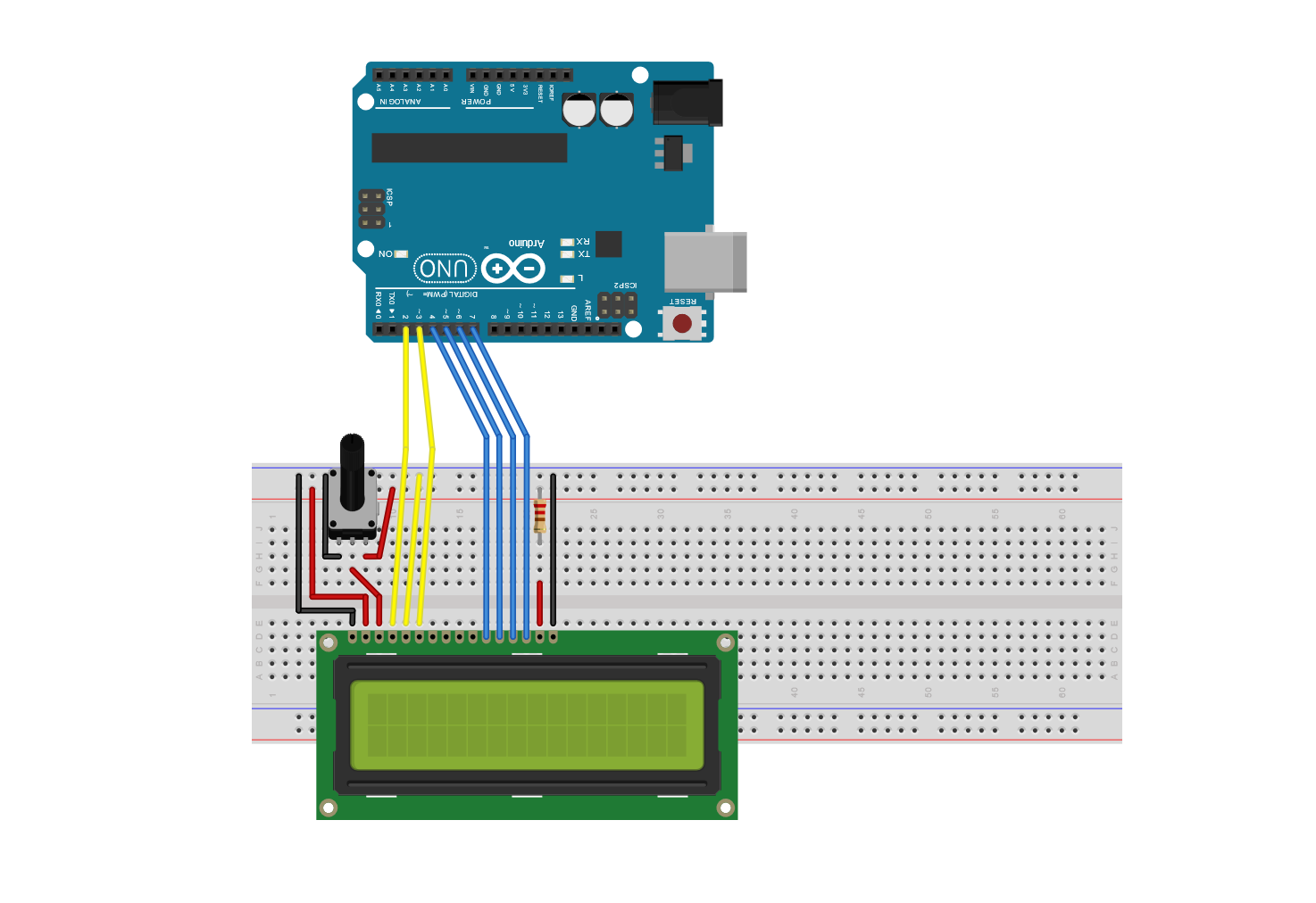
Once you are done with mounting the LCD to Modulus, we can then attach the male end of each jumper wire to the Uno’s female header pins. You should have 6 jumpers: one on pins 4, 6, and 11-14. Pins 4, 6, and 11-14 of the LCD will connect to Uno pins 2, 3, and 4-7, respectively.
If you are using a breadboard, a high-level schematic is shown below. We will be supplying +5V and GND to the breadboard via the FuelCan, which is described further in the next section.
If you haven’t mounted the Uno onto the prototyping area of the FuelCan, go ahead and do that. If you are using a breadboard instead of Modulus, place the breadboard in the bottom storage compartment to limit the length of the jumper wires. You’ll need to supply +5V and GND to the power and ground rails on the breadboard by using the provided banana jack to test-lead clip cables. You will need two male header pins to mount the test-lead clips on the breadboard side. Plug the Type A side of the USB cable into USB1 receptacle and the Type B side into the Uno’s receptacle. Plug in the AC-DC power adapter to power up the FuelCan.
SoftwareOnce the wiring is complete and the FuelCan is powered up, we can now load the sketch onto the Uno. The sketch is below. The LiquidCrystal library contains nineteen different functions that you can use. We don’t show you all of them, but we show the most commonly used ones such as lcd.print, lcd.clear, lcd.home, lcd.createChar, lcd.write, lcd.setCursor, lcd.blink, lcd.noBlink, lcd.cursor, lcd.noCursor, lcd.scrollDisplayLeft, and lcd.scrollDisplayRight. We even display a custom character on the LCD!


Comments
Please log in or sign up to comment.