*******
Please visit https://proteshea.com/interface-a-pir-sensor/ for a complete list of materials needed for this project.
*******
IntroductionIn this project, we’ll be replacing the DHT11 temperature and humidity sensor from Project 10 with a Passive InfraRed (PIR) sensor. The PIR sensor can detect movement up to 30′ away at 180 degrees. This can be useful in motion-activated projects such as a security system or automatic lighting in an office or classroom.
16x2 Character LCDPlease see our project "Interface a 16x2 Character LCD" on how to interface the 16×2 LCD in 4-bit mode. You should have pins 4, 6, and 11-14 of the LCD connected to Uno pins 2, 3, and 4-7, respectively. The LCD is mounted to the Modulus Canister via the 16-pin, right-angle female header soldered to the 1-to-1 link, as shown in the image below.
You can also connect the LCD to a solderless breadboard, as shown in the image below.
The PIR sensor that we are using consists of 4 pins: GND, VCC, OUT, and EN. It can measure movement up to 30′ away which can be adjusted with the potentiometer on the module. Within the dome-shaped lens (used to focus the incoming light onto the detectors), there are two slots that can detect different levels of infrared (IR) light or radiation. The sensor does not detect motion when the detectors sense the same amount of IR. The motion is detected when the detectors measure two different levels of IR. The levels of IR can vary from object to object since each one emits different amounts of heat energy.
A table is shown below that outlines the specifications for the PIR sensor that we are using. The datasheet is also available here.
If you completed our previous project "Displaying Temperature and Humidity on an LCD", remove the DHT11 sensor and insert the PIR sensor. You should have the 4-pin R/A female header soldered to Modulus. There should also be a 4-pin single-row male header soldered adjacently to the R/A female header. This is used so we can wire-wrap. You have to create a solder bridge between each contact to connect the respective pins on the female header to the male header.
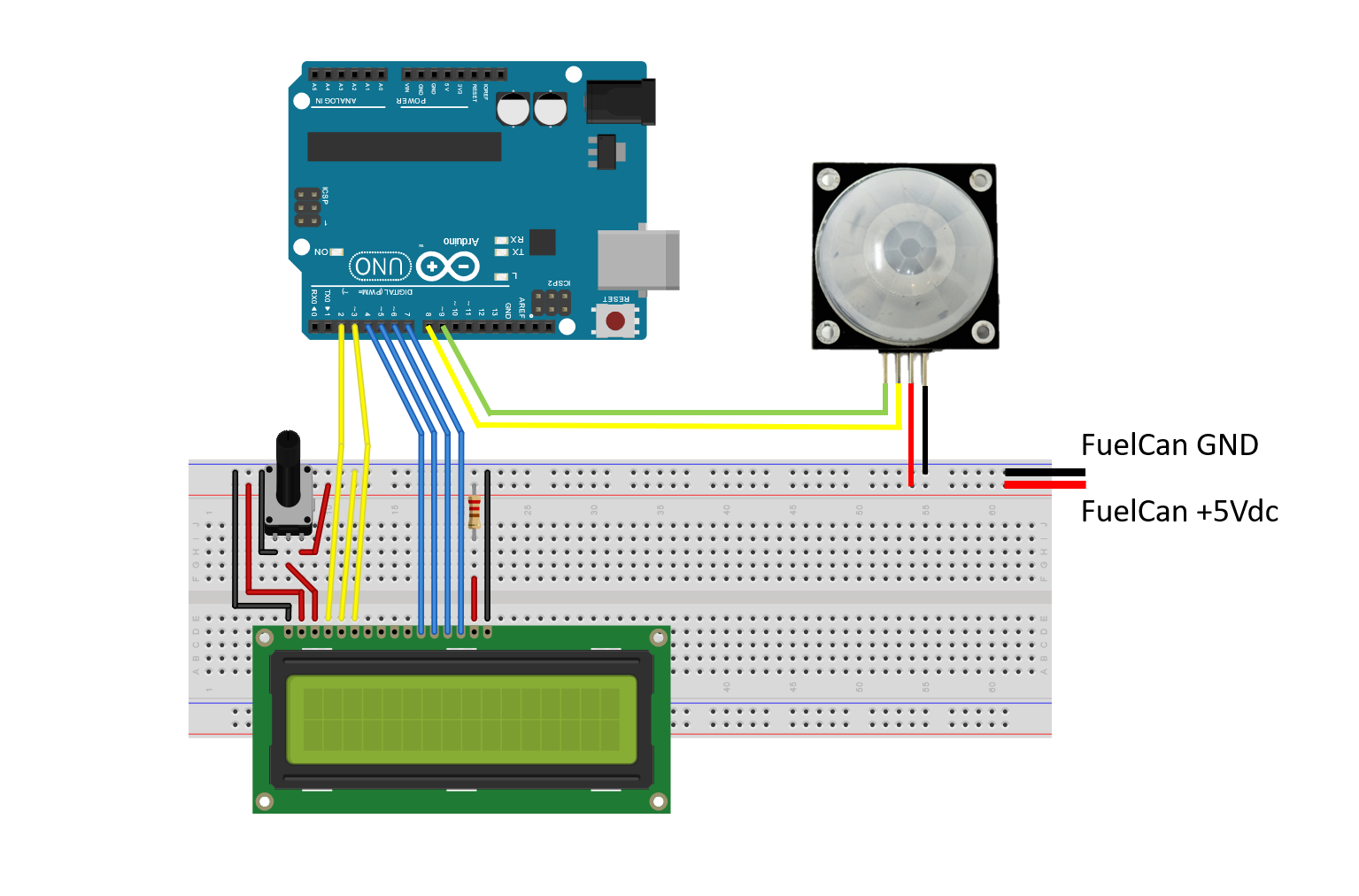
Once the headers are soldered on, plug the Modulus Canister into the 4×26-pin connector on the FuelCan, and insert the PIR sensor as shown below. Using the image below as reference, wire-wrap the leftmost pin of the male header to the GND vector on Modulus and the second pin from the left to +5Vdc on the 4×26-pin breakout. The third and fourth pins from the left are OUT and EN, respectively. Use a 12″ F/M to route the OUT pin to pin 8 on the Uno, and the EN pin to pin 9 on the Uno.
If you are using a solderless breadboard, the wiring schematic is shown below.
If you haven’t mounted the Uno onto the prototyping area of the FuelCan, go ahead and do that. If you are using a breadboard instead of Modulus, place the breadboard in the bottom storage compartment to limit the length of the jumper wires. You’ll need to supply +5V and GND to the power and ground rails on the breadboard by using the provided banana jack to test-lead clip cables. You will need two male header pins to mount the test-lead clips on the breadboard side. Plug the Type A side of the USB cable into USB1 receptacle and the Type B side into the Uno’s receptacle, so we can power and program the Uno. Power up the FuelCan with the AC-DC power adapter.
SoftwareOnce the wiring is complete and the FuelCan is powered up, we can now load the sketch onto the Uno. The sketch is below. The PIR sensor is enabled in void setup (). In void loop (), the OUT pin from the sensor is polled – if the pin goes HIGH, “Motion detected” is displayed on the LCD. If the OUT pin is LOW, “No motion” is displayed on the LCD.
There is a nomotionflag within the sketch which limits the amount of times we write to the LCD. For example, if the flag equals zero, we display “No motion” on the LCD. Once it is displayed, the flag gets set to one and it will not keep writing “No motion” if no movement is detected. When movement is detected, the flag gets reset to zero, and “Motion detected” is displayed on the LCD.


Comments
Please log in or sign up to comment.