


Hardware components | ||||||
 |
| × | 1 | |||
 |
| × | 4 | |||
 |
| × | 1 | |||
 |
| × | 1 | |||
 |
| × | 1 | |||
 |
| × | 1 | |||
 |
| × | 1 | |||
 |
| × | 1 | |||
Software apps and online services | ||||||
 |
| |||||
What is Mppt ( Maximum power point tracking)?
We use the MPT algorithm to Extract the maximum available power from the Photovoltaic module under certain conditions. MPPT is a Most Popular tool that helps us to use Solar Energy (Renewable Energy Source) in an efficient way. If we want to Reduce the Graph of Carbon footprints then we must need to move towards clean energy which is called Renewable Energy ( Energy we can get from Natural resources) Like SOLAR, HYDRO, WIND e.t.c otherwise we will directly move toward Global Warming.
Every Country needs to Move towards Green Energy especially the CHINA because it is the Main contributor by producing 63% Co2.
How MPPT works? Why 150W solar panel does not equal to 150 w?
For example, you bought a new solar panel from the market which can deliver 7 amps current, under charge the setting of a battery is configured to 12 volts: 7 amps times 12 volts = 84w (P=V*I) You lost over 66 watts - but you paid for 150 watts. That 66 watt is not going anywhere, but it,s due to the poor match of the solar output current and battery voltage.
After using MPPT algorithm we can get the Maximum available power Battery gets is now 12 amps at 12 volts Output power is equal to p= V*I p=12*12=144w Now you still have almost 144 watts, and everyone is happy.
Specification of the project
2. LED indication to show the low mid and high level of charge stat
3. LCD (20x4 character ) display for displaying power,current,voltages etc
4. Lightning /Overvoltage Protection
5. Protection For Reverse power flow
6. Overload & Short Circuit Protection
7. Logging data through WiFi
8.Charge your Cellphone, tablets any gadgets through USB port
Electrical specifications:
1.Rated Voltage= 12V
2.Maximum input current = 5A
3.Load current support up to =10A
4. Input Voltage = Solar panel 12 to 24V
5.power of Solar panel = 50 Watts
PARTS REQUIRED:- Resistors ( 3 x 200R ,3 x330R,1 x 1K, 2 x 10K, 2 x 20K, 2x 100k, 1x 470K )
- TVS diode ( 2x P6KE36CA )
- Arduino Nano
- ( ACS712-5A ) Current Sensor
- Buck Converter ( LM2596 )
- Wifi Module ( ESP8266 )
- LCD display ( 20x4 I2C )
- MOSFETs ( 4x IRFZ44N )
- MOSFET driver ( IR2104 )
- 3.3V Linear regulator ( AMS 1117 )
- Transistor ( 2N2222 )
- Diodes ( 2x IN4148 , 1 x UF4007 )
- Capacitors ( 4 x 0.1 uF, 3 x 10uF ,1 x100 uF ,1x 220uF)
- Inductor ( 1x 33uH -5A )
- LEDs ( Red, Yellow, Green )
- Fuses ( 5A)
Libraries Required For Arduino IDE :
- TimerOne.h - Click Here To Download This Library
- LiquidCrystal_I2C - Click Here To Download This Library
Remember: Make a New Folder ( Folder name should be same as library names like TimerOne and LiquidCrystal_I2C. Paste these Two Folders in Arduino/LIbrary.
---------------------------------------------------------------------------------
Model of Arduino Based MPPT Algorithm Charge ControllerSimulation of MPPT Charge Controller Project in Proteus software
This Simulation has been designed in Proteus Software 8.6 version. You can make your own by using Arduino Library for Proteus and a simulation tool known as Proteus. Kindly Contact Us if you want to Buy a proteus simulation source file for this project.
WiFi Data Logging by using a Wifi module ESP8266
Read This Article: Learn How to Setup the Wifi Module ESP8266 by Using Just Arduino IDE
After Reading The Above article I am assuming that you have successfully connected your ESP8266 module to your Wifi.
- Go and Sign Up in https://thingspeak.com/
- Make a New Channel and write "Solar Panel Data" in Field 1 and leave other fields blanks and save it.
- You will Get API key, Copy that Api Key and Paste in Source Code.
- Done
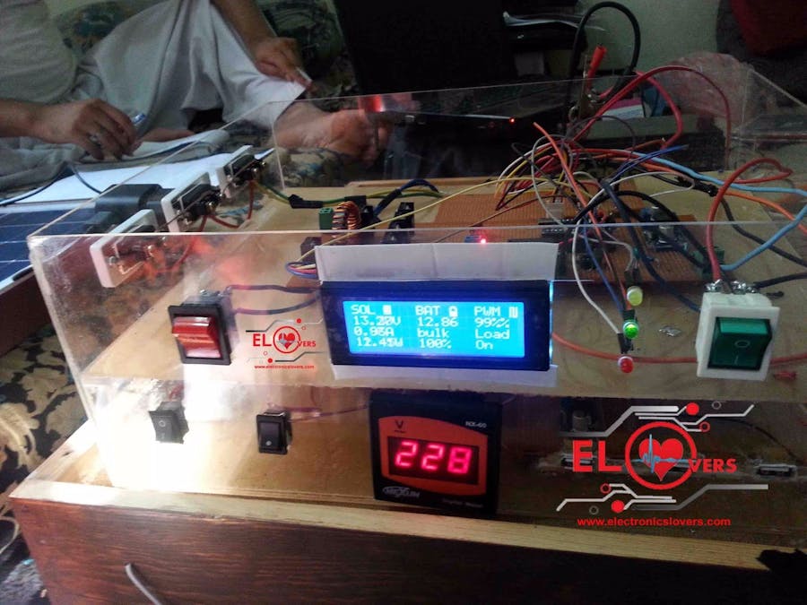
Project Images
"Do not forget to install all the necessary libraries before uploading the code to Arduino Nano "
Schematic Diagram:
If you found any difficulty while making this project so don't hesitate to ask first we are here to help you 24 hours a day and 7 days a week 24/7 thanks


_3u05Tpwasz.png?auto=compress%2Cformat&w=40&h=40&fit=fillmax&bg=fff&dpr=2)


Comments
Please log in or sign up to comment.