Our initial project was to build an electric skateboard from scratch, that we would control with a slider in an app on our phone. However, this first required being able to send a PWM signal via Bluetooth to the Arduino, as well as a command to reverse the motor's direction. Being an Arduino novice, I first had to scour the internet in search of projects that would serve as stepping stones towards creating my own project, so as to learn key concepts and apply them. This is the result of a few weeks of learning Arduino from the very beginning, and I'll be happy to know if this has in turn helped anyone learn a thing or two!
This build is the small scale prototype of what would be used on a skateboard, and should be scaleable with minor modifications. I'll first give the required parts as well as some explanation behind them, then the electrical circuit as well as the accompanying code, and at the end will be instructions on how to customize the app to work with the program.
Required partsYou will need:
- an Arduino Uno or Nano;
- a Bluetooth Low Energy (BLE) module, such as the HC-06 which is a slave only, or the HC-05 that can be a master or slave. Either will work because the module will be used as a slave. They also share the same four middle pins, which are the only ones we need;
- an L293D motor driver IC. This 16 pin dual H-bridge motor driver will allow us to control the spinning direction and speed of the motor;
- a 12V DC motor;
- a 12V battery pack;
- a power source for the arduino;
- jumper wires and a breadboard.
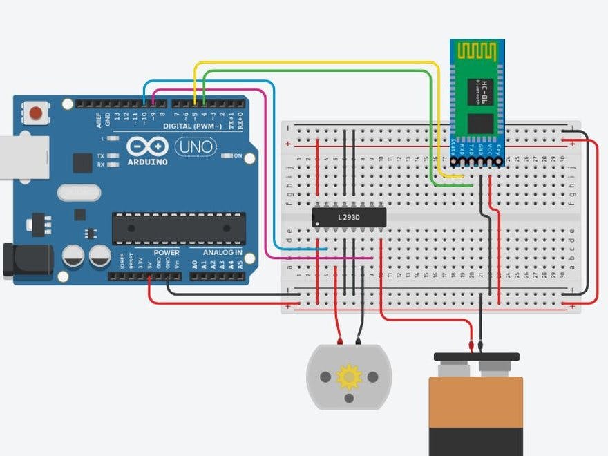
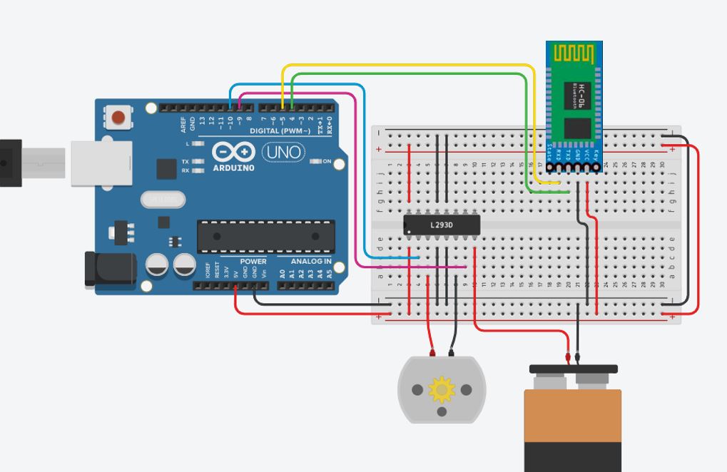
The HC-06 will be receiving serial data when sent out from the master bluetooth device, which will be communicated to the Arduino through its receive/transmit pins, RX/TX, connected to pins 5 and 4 of the board. Its GND and VCC pins will be respectively connected to GND and +5V.
The H-bridge in the L293D will allow us to control the rotational direction of the motor, by opening or closing a pair of switches, 4 of which are arranged in the shape of an H, hence the name.
This motor driver is also capable of driving two motors at different speeds, but only one will be used for this project.
To enable the motor, connect "Enable 1, 2" (pin1) and "Vcc1" (pin 16) to +5V. Connect "Vcc2" (pin 8) to the positive of the 12V battery pack. Connect pins 4, 5, 12 and 13 to GND. Connect "Input 1" (pin 2) to pin 10 of the Arduino, which will transmit the pwm2 signal, and "Input 2" (pin 7) to pin 9, for pwm1. Switching between these will allow us to switch the rotational direction. Finally, connect the DC motor to outputs 1 and 2 (pins 3 and 6).
Here is a picture of what it should look like when connected on a breadboard:
Commentaries have been added to help explain the code, but some more clarification may be needed.
pwm1 and pwm2 are opposites, and allow us to switch the rotational direction. The serial data sent by the app is a string, c, which is where the speed and direction data will be. In order to make this work, the speed is located in c[1], c[2] and c[3] of the string, which is why it must be received as a 3 digit number. That is why in the app, we customize the slider to send a number between 100 and 255. This can then be mapped out onto [0:255] in the Arduino under a new speed variable like so:
new_speed = map(speed_value,100,255,0,255)
We however decided to simply subtract 100 from speed_value, for the speed to belong to the interval [0:155], as 155 was fast enough for our prototype.
#include<SoftwareSerial.h>
SoftwareSerial bt_ser(4,5); //connected to RX and TX pins for serial data communication
char c[6];
int i=0,speed_value=0,send_value;
#define pwm1     9   //input 2
#define pwm2    10   //input 1
boolean motor_dir = 0;
void setup()
{
 Serial.begin(9600);
 bt_ser.begin(9600);
 pinMode(pwm1,   OUTPUT);
 pinMode(pwm2,   OUTPUT);
}
void loop()
{
  while(bt_ser.available())   //when data is transmitted
    {
      if(bt_ser.available()>0)
      {
        c[i] = bt_ser.read();   //reading the string sent from master device
        Serial.print(c[i]);
        i++;
      }
      if(c[i-1]=='N')    //if button is pressed
       {
         motor_dir = !motor_dir;     //toggle direction variable
         if(motor_dir)               //setting direction, pwm1 and pwm2 are opposites
           digitalWrite(pwm2, 0);
         else
           digitalWrite(pwm1, 0);
       }
     }
      speed_value = (c[1]-48)*100+(c[2]-48)*10+(c[3]-48)*1;  //interpreting speed from string
      if(motor_dir)   //for a given direction
         {
           if(c[i-1]=='#'){   //if data has been transmitted from slider
             analogWrite(pwm1, speed_value-100);  //-100 so that when slider is on "0" speed is 0
             i=0;
           }
         }
       else{       //for opposite direction
         if(c[i-1]=='#'){
           analogWrite(pwm2, speed_value-100);
           i=0;
         }
       }
}
We decided to use an application called Bluetooth Electronics that we found on the Play Store, because it gives the option to create dashboards as well as customizing the data the components on the dashboard send, or how they interact with each other.
In order to create this interface, you will need to edit a new dashboard, and from the editing menu select a slider, a button and a text box.
The slider will have to be edited as so:
- Min value: 100
- Max value : 255
- Send string on slider change
- String starts with : *
- String ends with : #
The button should be edited as so (release text left as blank) :
- Press text : N
- Release text :
You can then add text to clarify the dashboard.
The ResultSome lessons I learned as a beginnerAs we created this project, I gained some wisdom that I thought I might share with other Arduino beginners, because although some of this will probably sound obvious, it came as a steep learning curve for me.
1. When building a project with a supplied program found online, always make sure to tweak the code and test it to understand what all the parts do. I often stripped down code to try to isolate certain functions and see how to do them differently, and by doing so I understood the way these codes worked much better, and was able to take inspiration from them to create something new myself, as opposed to simply copy and pasting an entire program.
2. This one sounds obvious but I made this mistake numerous times : components that look alike are not always the same! I especially made this mistake when using transistors and dual in-line packages like the L293D. Having similar looking components on hand, I tried building circuits, but they never worked, and it took having to order the correct components to get them to function.
3. When you're stuck on something, a bit of targeted internet research can solve most issues, it just takes some patience reading and understanding, whether it be about code elements or electrical components.
ConclusionIf you are inspired to build this project, I would recommend taking the liberty to modify it to better suit your goals and learn more about how to create your own Arduino project. As it was a prototype of an electric skateboard motor control system, here are some potential ideas and examples we thought of that could be implemented:
- an on/off switch;
- a requirement to drag the slider to the "0" position before being able to activate the reverse button;
- a brake command (gradual stop as opposed to immediate stop from off or reverse button, or having to gradually slide the speed down manually);
- even creating your own mobile app to control the motor, as we used one that was available on the appstore. MIT app inventor seems likea good platform to create such an app;
- a handheld remote control could also replace the mobile phone, and in the case of an electric skateboard, would certainly be a safer option;
- we also thought that adding a pressure sensor on the skateboard deck could allow the implementation of an emergency stop in case the user fell off, although a distance reading between the remote and Arduino could also accomplish that goal, stopping it once the remote/user is too far.
Always remember to be safe, this is only a small scale prototype of an electric skateboard's motor control system, which we have not attempted to use on an actual one, and we do not recommend using it for that purpose, as it is untested on a real skateboard and could be hazardous.
We hope this has been helpful and that you'll have fun with the project!


_ztBMuBhMHo.jpg?auto=compress%2Cformat&w=48&h=48&fit=fill&bg=ffffff)


Comments
Please log in or sign up to comment.